In this step, we will work with the Control FPWIN Pro7 example that can be downloaded from the TLS Client/Server page in the FP-I4C units's application settings.
Create a project with the Control FPWIN Pro7 example.
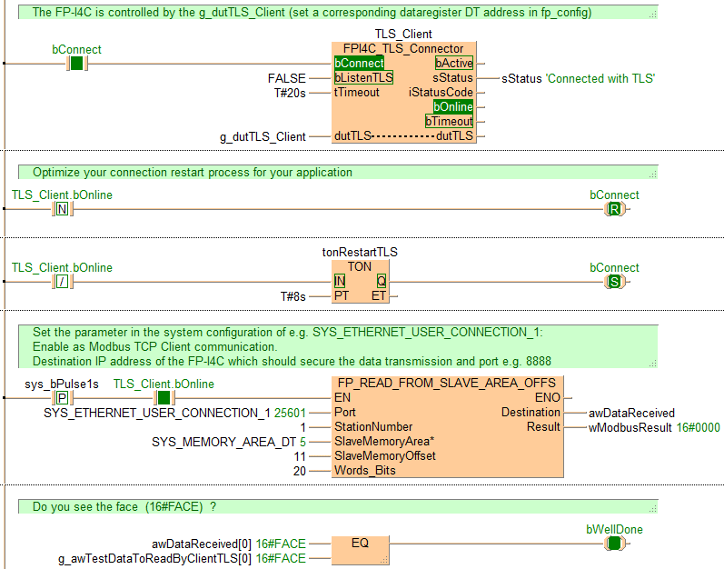
Check the Tasks and enable ClientTLS (disable ServerTLS). This POU is used to control the client part.
Use the function block FPI4C_TLS_Connector of the FP-I4C library for Control FPWIN Pro7. For the client part, the input bListenTLS must be FALSE.
When bOnline of the function block FPI4C_TLS_Connector turns TRUE, communication can start. The Modbus data transmission is performed by the function FP_READ_FROM_SLAVE_AREA_OFFS.
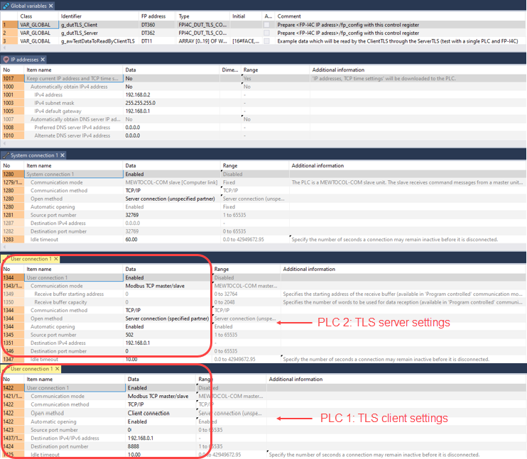
This example runs on user connection 1, which must be configured as follows:
The data fetched from ‘Read Holding Register’ is stored in awDataReceived.
Finally, as a test, we can compare the result with the preset data stored in g_awTestDataToReadByClientTLS.
Create a second project with the same Control FPWIN Pro7 example.
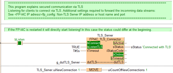
Check the Tasks and enable ServerTLS (disable ClientTLS). This POU is used to control the server part.
Use the function block FPI4C_TLS_Connector of the FP-I4C library for Control FPWIN Pro7. Set the input bListenTLS to TRUE.
Use the function block to monitor the status.
In our example, the decrypted data will be forwarded from the FP-I4C unit via ETH1 to the configured user connection 1 of the PLC (Modbus TCP server port 502).
Except for some address settings, no additional configuration or program code is needed in the PLC.
Check the addresses in the global variables.
Check the IP address of the PLC. We recommend to use a private zone. If you want to use another IP address, you must also configure it later in the FP-I4 unit.
Check the system connection port for the Control FPWIN Pro7 communication (32769 is the default setting).
Make sure the IP address and port of the user connection used to transmit the plain Modbus TCP requests match your FP-I4C settings.
Compile your program.
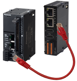
Install the Ethernet cables between ETH1 of the FP-I4C unit and the PLC. This network is a private zone for the PLC and the FP-I4C unit.
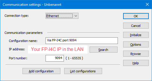
Control FPWIN Pro7 can be connected either in the private zone or in the LAN via DHCP.
To go online, use the settings according to the network used and transfer the sample program to the PLC.