Panasonic FP Series PLCs use addresses from which you can read data or to which you can write data. Both bit and word addresses are used.
Bit addresses
If, for example, you wish to provide the address of the first unit’s (an input unit) first input and the second unit’s (an output unit) fourth output, the FP address for an FP1 is X0 (1st input) and Y3 (4th output).
For internal memory areas, supply the reference letter and the number of the memory area as the FP address, e.g. R9000 for the 9000 link or DT9001 for the 9001 data register. The addresses for the memory areas are contained in your hardware description.
Word addresses
Individual bit addresses for inputs (X), outputs (Y) and flags (R) can also be saved in words. 16 bits form a word. A word address containing 16 flags looks like this:
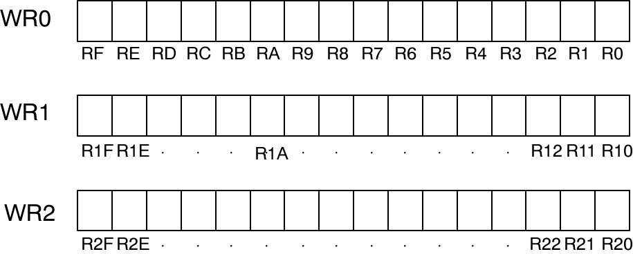
The bits are numbered hexadecimally from right to left. How the individual bits are assigned can be seen from the 3 flag words WR0 to WR2:
R5 is the 6th bit in word WR0
R1A is the 11th bit in word WR1
R2E is the 15th bit in word WR2
When the status of a bit changes, the value of the whole word changes.