PANATERM – Ethernet over EtherCAT (EoE)
Before you start
Before operating this product, read the safety instructions in the following manuals:
This product is for industrial use only.
Electrical connections must be made by qualified electrical personnel.
Description
A PC can be used as a host controller to perform Ethernet communication via EtherCAT (EoE) with a MINAS A6 Multi servo drive system. Step by step instructions will guide you through installing Beckhoff’s TwinCAT 3 software to configure the EtherCAT functionality on your PC. And you will learn how to connect the PC configuration software PANATERM with the MINAS A6 Multi servo drive system via EtherCAT.
Available software
The following software is available free of charge in our Panasonic Download Center.
The following software can be downloaded from Beckhoff’s Web site (https://www.beckhoff.de):
TwinCAT3 Engineering software (Go to )
Functional overview
A Panasonic MINAS A6 Multi servo drive system includes a power supply module, one or more 400V driver modules, and one or two motors connected to each driver module. Communication can be achieved through EtherCAT with any host controller that supports the CAN application protocol over EtherCAT (CoE).
With Beckhoff’s TwinCAT 3 software, a PC can be configured as an EtherCAT host controller. The PC configuration software PANATERM is used to perform the communication with the MINAS A6 Multi servo drive system.
Example
A servo drive system, consisting of a 15kW power supply module, an A-size 1.5kW two-axis driver module, and two servo motors with a rated power of 1.0kW and 1.5kW, is connected to a PC by an Ethernet cable to communicate via EoE.
Use the following accessories:
1 x 400V AC power supply cable: Connects the MINAS A6 Multi power supply module to the main power supply (400V AC).
1 x 24V DC power supply cable: Connects the power supply unit (24V DC) and the host controller.
1 x grounding wire (M4 round terminal): Connects the PE terminals of the power supply module and the driver module.
2 x Panasonic motor cable: Connects the motor and the driver module.
2 x Panasonic encoder cable: Connects the encoder and the driver module.
1 x Ethernet cable (RJ45): Connects the PC and the driver module.
1 x RJ11 communication cable (2 x RJ11 plug): Connects the power supply module and the driver module.
1 x feed bus bar (50mm) with end cap for the DC link bus (535V DC to 675V DC): Connects the power supply module and the driver module.
1 x feed bus bar (50mm) with end cap for the control bus (24V DC): Connects the power supply module and the driver module.

- (1) Power supply unit (24V DC)
- (2) MINAS A6 Multi power supply module (400V AC, 15kW)
- (3) Two-axis MINAS A6 Multi driver module (1.5kW)
- (4) MINAS A6 servo motor B (1.5kW)
- (5) MINAS A6 servo motor A (1kW)
- (6) PC with TwinCAT 3 Engineering software and PANATERM
Wiring
Recommendations for wiring
It is the customer's responsibility to apply the countermeasures that they consider necessary to comply with current regulations on wiring, safety and reducing EMI.
Do not forget to meet the specifications indicated in the hardware manual for each of the devices being wired. If any specifications in the manual conflict with the information in this document, the manufacturer's manual takes preference.
For detailed information on reducing EMI, please refer to Recommendations for EMC-compliant wiring of servo drivers and motors.
Bottom side connectors of the servo drive system
The image shows the most important connectors of a power supply module (left) and a driver module (right). Please refer to the technical documentation for details about other connectors.

- (1)
X102: Main power supply (400V AC)
Connect the 400V AC main power supply cable to X102. Connect the PE terminals of the power supply module and the driver module by a grounding wire.
- (2)
X11: Control power supply (24V DC)
Connect the 24V DC control power supply to X11.
- (3)
X105A: Motor A, (4) X105B: Motor B
Connect the motor cable for servo motor A to X105A and the motor cable for servo motor B to X105B.
- (4)
X9A: Encoder A, (6) X9B: Encoder B
Connect the cable of encoder A to X9A and the cable of encoder B to X9B.
Top side connectors of the servo drive system
The image shows the most important connectors of a power supply module (left) and a driver module (right). Please refer to the technical documentation for details about other connectors.

- (1)
X1: Internal communication connector on power supply module, (2) X1A: Internal communication connector on driver module
Connect X1 and X1A with the RJ11 communication cable.
- (3)
X6A: EtherCAT communication connector on driver module (not used in this example)
Connect an Ethernet cable between the PC and the EtherCAT connector (X6A) of the driver module.
Front side connectors of the servo drive system
The image shows the most important connectors of a power supply module (left) and a driver module (right). Please refer to the technical documentation for details about other connectors.

- (1)
X7: USB connector (for driver configuration) on driver module
The driver module is configured using the PC configuration software PANATERM. Use a commercially available USB A to mini-B cable to connect the PC to the driver module.
- (2)
X104: DC link bus connectors on power supply module and driver module (535V DC to 675V DC), (3) X12: Control bus (24V DC) connectors on power supply module and driver module
Attach the bus bars to X104 and X12 to connect the DC circuits of the power supply module and the driver module.
- (4)
Connectors for DC circuits without and with bus bars
Set up the host controller
Set the IP address in your PC
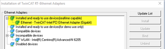
Check the EtherCAT driver installation
- Make sure the Ethernet network adapter is displayed under Installed and ready to use devices (realtime capable).
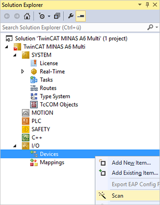
Add connected devices to your project
You must add the connected devices to your TwinCAT project.
- In the Solution Explorer, go to I/O and right-click on Devices. Select Scan.
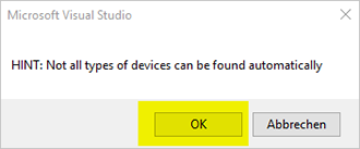
- Confirm the message that not all devices can be found automatically.
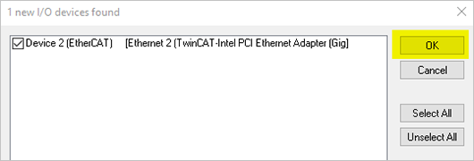
- When the EtherCAT master device is found, select OK.
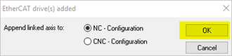
- When the MINAS A6 Multi driver module is found, the following message comes up that you confirm with OK.
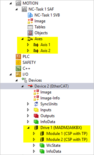
- The Solution Explorer displays the added driver module with its two connected motors under . It also displays all found axes under .
Activate the EoE functionality in your TwinCAT project
Make settings for the EtherCAT master:
- Select Connect to TCP/IP Stack under Windows Network.
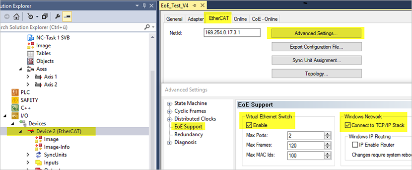
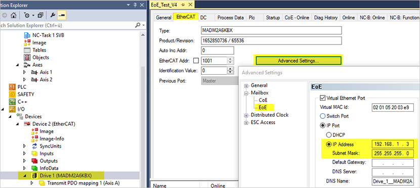
Make settings for EtherCAT slave:
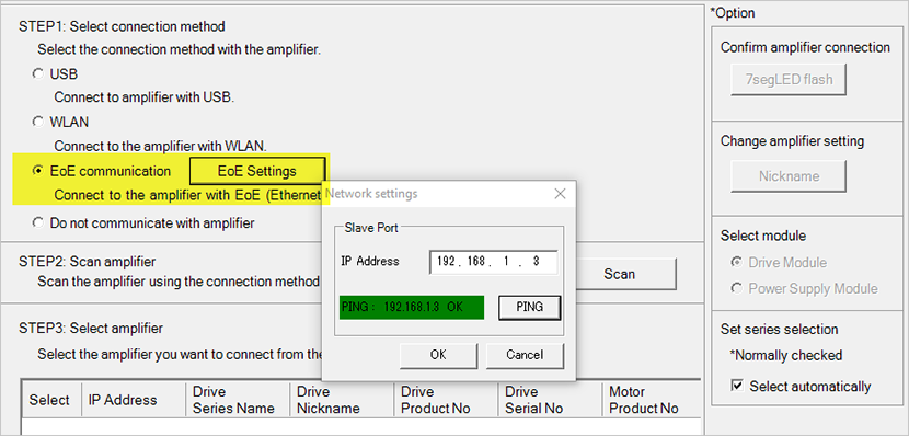
- Set the IP address and subnet mask in the EoE section. Make sure the IP addresses of the MINAS A6 Multi driver module and the PC are in the same subnet.
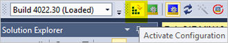
- Select the Activate Configuration icon from the toolbar.
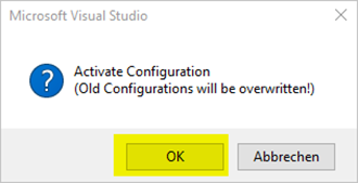
- Confirm the message that the new configuration will be activated and old configurations will be overwritten.
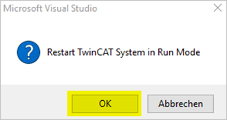
- Confirm the message that the TwinCAT system will be restarted in run mode.
The TwinCAT system is now in run mode and the corresponding icon is active.
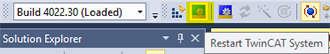
(To switch back to configuration mode, select the blue icon on the right of the green icon.)
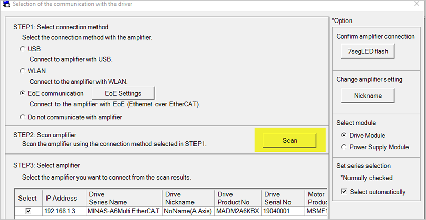
Connect PANATERM via EoE
- Select OK.
- Select Scan to search for the driver module. Then select the driver module and close the window with OK.
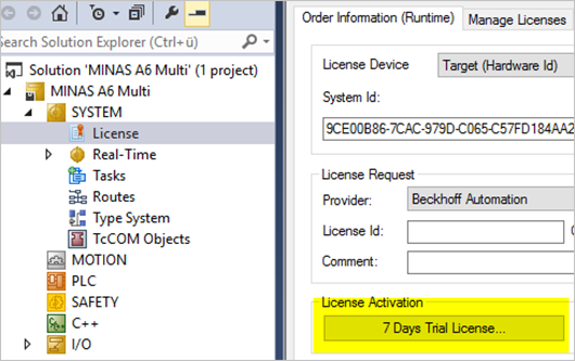
Activate the TwinCAT Runtime software license
The TwinCAT Runtime software is free of charge for 7 days. The trial license can be renewed as needed.
- Go to the Order Information (Runtime) tab and select 7 Days Trial License.