PANATERM for Safety – Safe Speed Monitoring (SSM)
Before you start
Before operating this product, read the safety instructions in the following manuals:
This product is for industrial use only.
Electrical connections must be made by qualified electrical personnel.
Description
Step by step instructions will guide you through configuring and programming the Safe Speed Monitoring function (SSM) with the programming software PANATERM for Safety.
Available software
The following software is available free of charge in our Panasonic Download Center.
Functional overview
Use the Safe Stop Monitoring function (SSM) to monitor the speed of the drive and to output a signal when the speed drops below a specified threshold.
Use the programming software PANATERM for Safety to set up this function for the MINAS A6 Multi servo drive system.

- (1) Enabled
- (2) Result output
[t0, t1[ |
Speed is above the parametrized threshold. SSM result is "0". |
[t1, t2[ |
Speed is below the parametrized threshold. SSM result is "1". |
[t2, t3[ |
Speed is above the parametrized threshold. SSM result is "0" again. |
[t3, t4[ |
Speed is below the parametrized threshold. SSM result is "1" again. |
Example
A servo drive system, consisting of a 15kW power supply module, an A-size 1.5kW two-axis driver module, and two servo motors with 1.0kW and 1.5kW, is connected to a PC by a USB cable.
Use the following accessories:
1 x 400V AC power supply cable: Connects the MINAS A6 Multi power supply module to the main power supply (400V AC).
1 x 24V DC power supply cable: Connects the power supply unit (24V DC) and the host controller.
1 x grounding wire (M4 round terminal): Connects the PE terminals of the power supply module and the driver module.
2 x Panasonic motor cable: Connects the motor and the driver module.
2 x Panasonic encoder cable: Connects the encoder and the driver module.
1 x RJ11 communication cable (2 x RJ11 plug): Connects the power supply module and the driver module.
1 x feed bus bar (50mm) with end cap for the DC link bus (535V DC to 675V DC): Connects the power supply module and the driver module.
1 x feed bus bar (50mm) with end cap for the control bus (24V DC): Connects the power supply module and the driver module.
1 x USB license dongle
1 x USB cable

- (1) Power supply unit (24V DC)
- (2) MINAS A6 Multi power supply module (400V AC, 15kW)
- (3) Two-axis MINAS A6 Multi driver module (1.5kW)
- (4) USB cable between PC and driver module
- (5) MINAS A6 servo motor B (1.5kW)
- (6) MINAS A6 servo motor A (1kW)
- (7) USB license dongle for PANATERM for Safety
- (8) PC with PANATERM for Safety
Wiring
Recommendations for wiring
It is the customer's responsibility to apply the countermeasures that they consider necessary to comply with current regulations on wiring, safety and reducing EMI.
Do not forget to meet the specifications indicated in the hardware manual for each of the devices being wired. If any specifications in the manual conflict with the information in this document, the manufacturer's manual takes preference.
For detailed information on reducing EMI, please refer to Recommendations for EMC-compliant wiring of servo drivers and motors.
Bottom side connectors of the servo drive system
The image shows the most important connectors of a power supply module (left) and a driver module (right). Please refer to the technical documentation for details about other connectors.

- (1)
X102: Main power supply (400V AC)
Connect the 400V AC main power supply cable to X102. Connect the PE terminals of the power supply module and the driver module by a grounding wire.
- (2)
X11: Control power supply (24V DC)
Connect the 24V DC control power supply to X11.
- (3)
X105A: Motor A, (4) X105B: Motor B
Connect the motor cable for servo motor A to X105A and the motor cable for servo motor B to X105B.
- (4)
X9A: Encoder A, (6) X9B: Encoder B
Connect the cable of encoder A to X9A and the cable of encoder B to X9B.
Top side connectors of the servo drive system
The image shows the most important connectors of a power supply module (left) and a driver module (right). Please refer to the technical documentation for details about other connectors.

- (1)
X1: Internal communication connector on power supply module, (2) X1A: Internal communication connector on driver module
Connect X1 and X1A with the RJ11 communication cable.
- (3)
X6A: EtherCAT communication connector on driver module (not used in this example)
Front side connectors of the servo drive system
The image shows the most important connectors of a power supply module (left) and a driver module (right). Please refer to the technical documentation for details about other connectors.

- (1)
X7: USB connector (for driver configuration) on driver module
The driver module is configured using the PC configuration software PANATERM. Use a commercially available USB A to mini-B cable to connect the PC to the driver module.
- (2)
X104: DC link bus connectors on power supply module and driver module (535V DC to 675V DC), (3) X12: Control bus (24V DC) connectors on power supply module and driver module
Attach the bus bars to X104 and X12 to connect the DC circuits of the power supply module and the driver module.
- (4)
Connectors for DC circuits without and with bus bars
USB license dongle
A USB license dongle is required to compile and download the functional safety configuration to the driver module. Connect the license dongle to a USB port of your PC.
USB license dongle
Connect the PC and the driver module
Connect your PC and the driver module with an Ethernet cable or with a USB cable. In this example, we use a USB cable that is connected to X8 of the driver module.
X8 connector (for functional safety configuration)
Use a commercially available USB A to mini-B cable to connect the PC to the driver module.

- (1) X8: USB connector on driver module
Functional safety configuration
Install PANATERM for Safety on your PC
Install the software on your PC.
For details, refer to the PANATERM for Safety Programming Manual SX-DSV03508.
Create a safety program
The general workflow for creating a safety program is to add the devices of your servo drive system to your project, to place them in the Terminal Scheme screen, and to configure the safety functions in theFunctional Scheme screen.
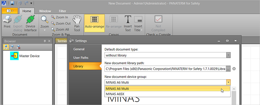
- Select the Settings tab.

- Select Library and then MINAS A6 Multi under New document device group.
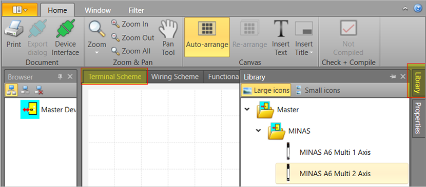
- Select MINAS A6 Multi 2 Axis from the Library window and drag the element into the Terminal Scheme window.
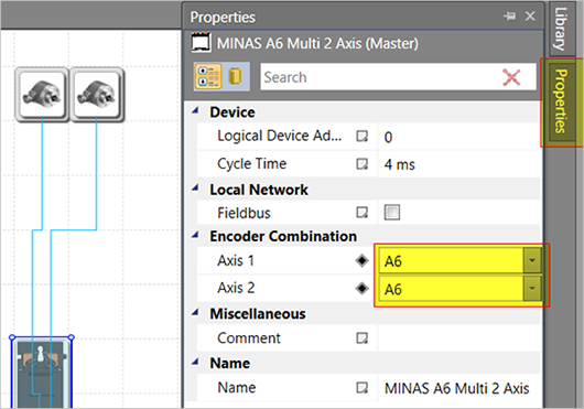
- Go to the Properties window and select the A6 encoder for both axes.
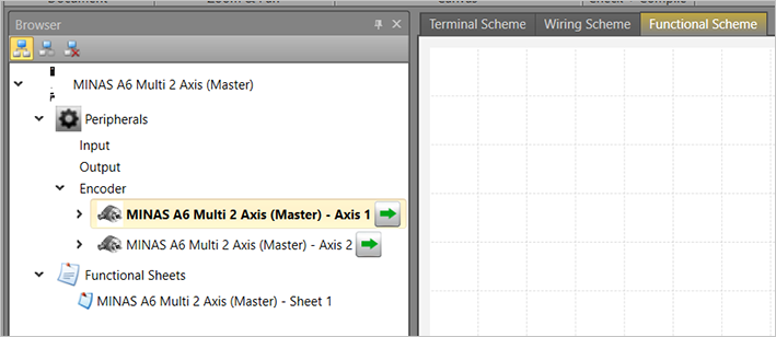
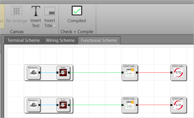
- Select the encoder elements from the Browser window and drag them into the Functional Scheme window.
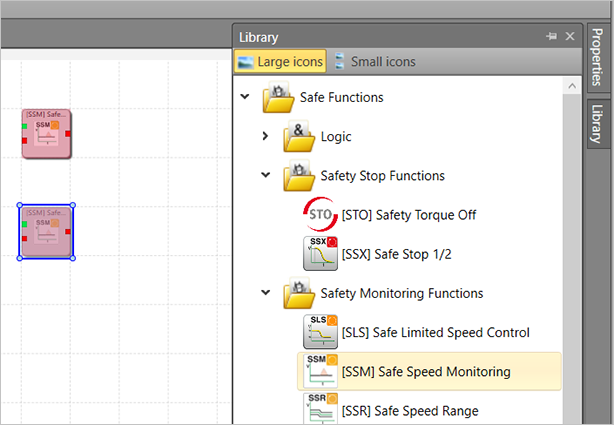
- Select the safety function [SSM] Safe Speed Monitoring from the Library window and drag it into the Functional Scheme window. For two axes, you need the function twice.
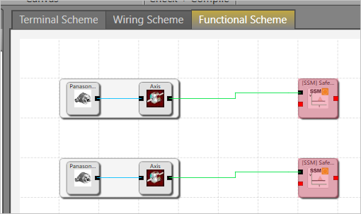
- Use the mouse to connect the elements.
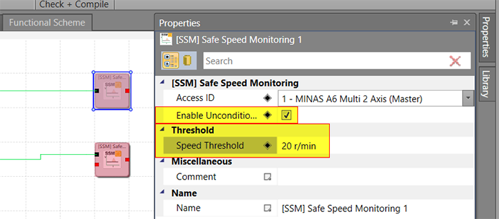
- Select the [SSM] function in the Terminal Scheme window, and make the settings in the Properties window as shown in the screenshot.The threshold value for speed is a sample value that can be adjusted according to the requirements of the machine.
- Select Check + Compile in the ribbon to compile your project
Download the safety program to the driver module
Remember that a USB license dongle is required to compile and save your program.
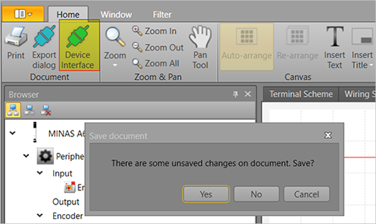
- Select Device Interface in the ribbon and save your project.
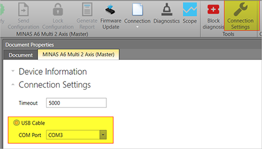
- Select Connection Settings in the ribbon and then USB Cable.
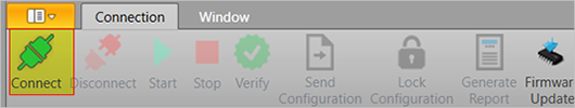
- Select Connect in the ribbon.
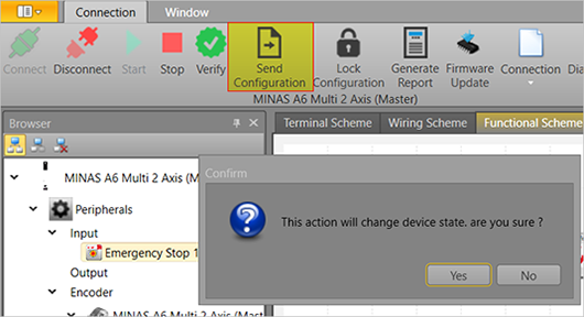
- Select Send Configuration in the ribbon.Select Yes to confirm the message that this action will change the device state.
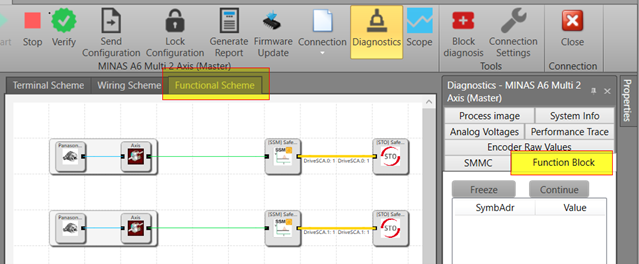
- To check the current status of the safety function, go to Diagnostics and select the Functional Scheme window.A yellow line means that the emergency stop button was not yet pressed. If it is red, the emergency button has been pressed and STO is active.
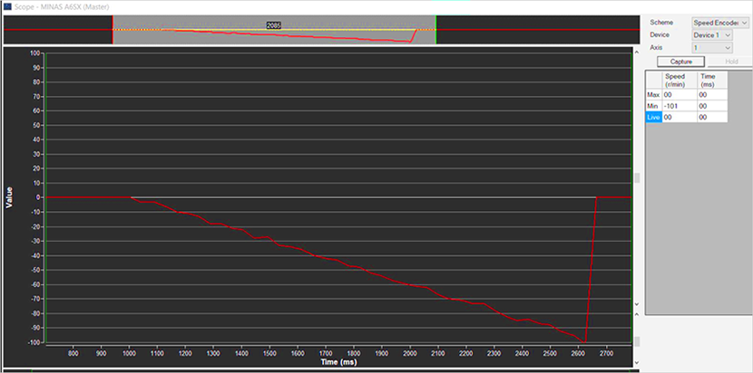
Monitor the behavior of the SSM safety function
You can adjust the threshold values set in the Properties window according to your needs. For details, refer to the SX-DSV03508, MINAS A6 Multi, Programming Manual – PANATERM for Safety.