Position control by block operation using input signals
Before you start
Before operating this product, read the safety instructions in the related Operating Instructions.
This product is for industrial use only.
Electrical connections must be made by qualified electrical personnel.
About this document
Step-by-step instructions will guide you through connecting a PLC to a MINAS servo driver and setting the most important parameters in the PANATERM configuration software.
Available software
The following software is available free of charge:
-
This link will take you to the Panasonic Industry Co., Ltd. Web site.
Control FPWIN Pro7 programming software (basic version)
This link will take you to the Control FPWIN Pro7 InfoHub.
Functional overview
Position control is a control mode in which the motor moves the load to a specified target position.
The servo driver can be controlled by a pulse train in the frequency range between 1Hz and 8MHz from a host controller such as a PLC or a CNC controller or by block operation. With block operation, the user defines the positioning parameters in block commands. The MINAS A6 servo driver has a block memory capacity of 256 block commands. All block commands are saved in a block operation table in the servo driver.
You can set the block commands using the PANATERM configuration software or by Modbus commands if you are using a PLC with a Modbus RTU port. The block commands are either started by digital signals from a PLC (e.g. STB, B-SEL1 to B-SEL128), a trigger switch, or by Modbus commands.
Example
An FP0H PLC and a MINAS A6SF servo driver are connected to control the driver by I/O signals. If needed, additional signals, such as servo-ready, alarm, or positioning complete, can also be transmitted.

- (1) Connect to external power supply.
- (2) Connect to limit switches.
Wiring
Recommendations for wiring
It is the customer's responsibility to apply the countermeasures that they consider necessary to comply with current regulations on wiring, safety and reducing EMI.
Do not forget to meet the specifications indicated in the hardware manual for each of the devices being wired. If any specifications in the manual conflict with the information in this document, the manufacturer's manual takes preference.
For detailed information on reducing EMI, please refer to Recommendations for EMC-compliant wiring of servo drivers and motors.
Connectors of the servo driver
XA connector (main power connector)
Connect the power supply cable to the XA connector. For a 1-phase power supply of 230V, connect a 2-wire cable to the servo driver as illustrated. The L2 pin is not used in 1-phase mode.

XB connector (motor connector)
Connect the motor cable to the XB connector. The wires are labeled with the letters U, V, and W. Do not change the sequence of the motor phases, e.g. by connecting V to W.

X6 connector (encoder connector)
Connect the encoder cable to the X6 connector.

X4 connector (I/O connector)
Connect the connection cable to the X4 connector and to the FP0H PLC. For PNP connections the preassembled connection cable DV0P0988WP-1 is available.
Panasonic provides different preassembled connection cables for connecting other PLC types.

- (1) Connect to external power supply.
- (2) Connect to limit switches.
X1 connector (USB connector for PC connection)
The servo driver is configured using the PANATERM configuration software . Use a commercially available USB A to mini-B cable to connect the PC to the servo driver.

Signal inputs and outputs of the X4 connector
For position control, the X4 connector of the MINAS A5/A6 servo driver is equipped with signal inputs and outputs.
Wiring of the pulse train input depends on your source of pulses (PLC, CNC, or motion controller):
- For open collector outputs of a PLC with a maximum frequency of 200kHz and a maximum pulse voltage level of 24V, you have two options:
With external resistor (12V or 24V power supply), use the pins 3, 4, 5, 6.
Without external resistor (24V power supply only), use the pins 1, 2, 4, 6.
For line driver outputs with a maximum frequency of 500kHz, use the pins 3, 4, 5, 6.
For line driver outputs with a maximum frequency of 8MHz, use the pins 44, 45, 46, 47.
In our example, we will use the following signal inputs and outputs:
SRV-ON (pin 29)
Servo-on input to energize the servo motor.
COM+ (pin 7)
Common input for the power supply of the control signals.
STB (pin number must be assigned in PANATERM)
Strobe input for starting block operation.
B-SEL1 to B-SEL128 (pin numbers must be assigned in PANATERM)
Block number inputs for selecting block commands.
S-RDY (pins 34–35)
Servo-ready output to indicate the ready state of the servo driver.
ALM (pins 36–37)
Servo-alarm output
INP (pins 38–39)
Positioning complete output which turns on when the target position is reached.
Please refer to the Operating Instructions of your MINAS A5/A6 servo driver to learn more about the signal inputs and outputs which might be useful for your application.

PNP wiring of the X4 connector

NPN wiring of the X4 connector

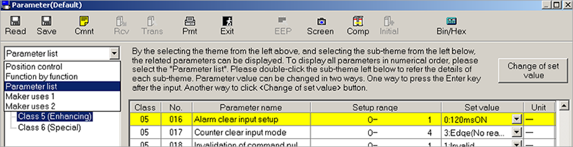
Make parameter settings in PANATERM
Use the PANATERM configuration software to configure the MINAS servo driver.
- Select the Parameter tab.
- Select the parameter list for your type of servo driver.
Basic parameters overview
The following table shows the setting range and description of the basic parameters.
Parameter |
Range |
Description |
|---|---|---|
Pr0.00 |
0 or 1 |
Motor rotation direction |
Pr0.01 |
0 to 6 |
Control mode |
Pr6.28 |
0 to 2 |
Block operation mode |
Pr0.00 (Motor rotation direction)
PANATERM parameter: Rotational direction setting
Setting range: 0 or 1
The default value is 1: Rotation in CCW direction (counterclockwise direction).
Pr0.01 (Control mode)
PANATERM parameter: Control mode setting
Setting range: 0 to 6
The default value is 0: Position control
Select 0: Position control (block operation mode only supports position control)
Pr6.28 (Block operation mode)
PANATERM parameter: Special function selection
Setting range: 0 to 2
The default value is 0: Block operation invalid
Select 2: Block operation valid (Input signal)
Make pin assignments in PANATERM
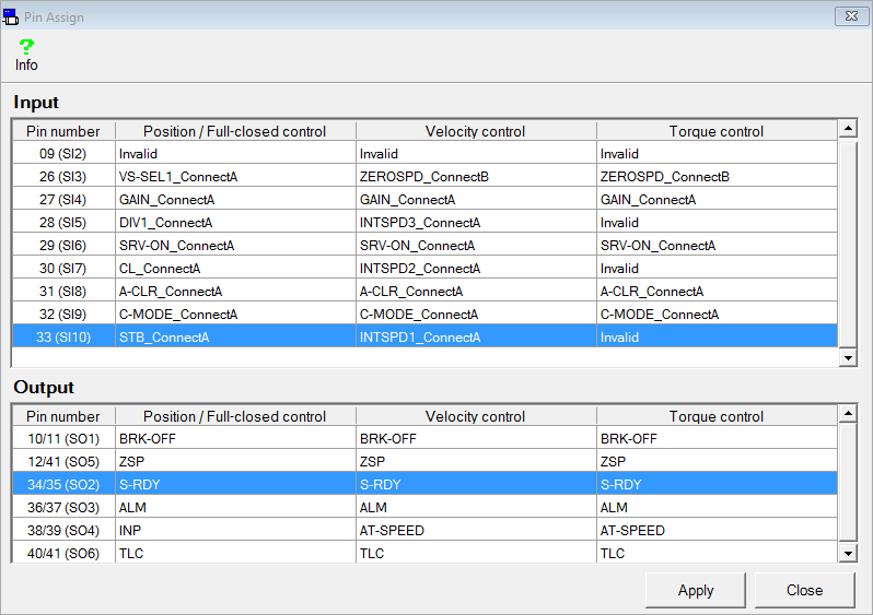
For some applications, the software function of physical pins of the servo driver must be changed. Use the PANATERM configuration software to make the pin assignment.
In this example, only the STB signal must be assigned to an input pin.
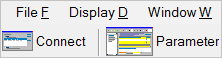
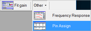
- Select .
The current pin assignment is uploaded from the servo driver.
- Select an arbitrary input which is not required by your application and double-click.
In this example, double-click on the line of pin number 33.
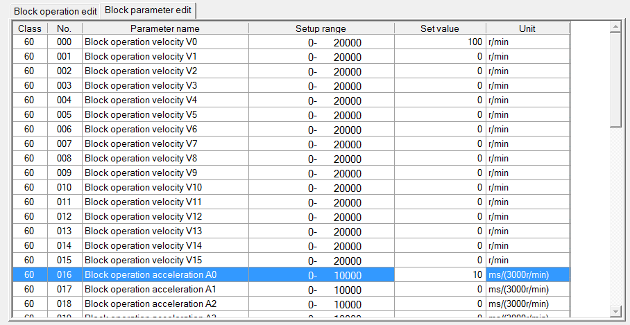
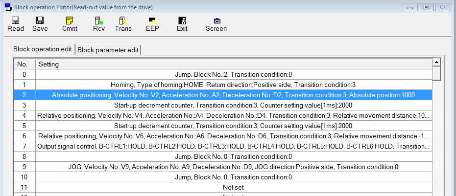
Enter block commands in PANATERM
To enter block commands, you need to start the block operation editor.
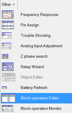
- Select .
- Select the desired command (e.g. JOG) and select OK.
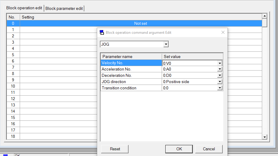
- Select the Block parameter edit tab to enter the desired values for velocity, acceleration, deceleration, etc.