Position control by block operation using Modbus commands
Before you start
Before operating this product, read the safety instructions in the related Operating Instructions.
This product is for industrial use only.
Electrical connections must be made by qualified electrical personnel.
About this document
Step-by-step instructions will guide you through connecting a PLC to a MINAS servo driver and setting the most important parameters in the PANATERM configuration software.
Available software
The following software is available free of charge.
-
This link will take you to the Panasonic Industry Co., Ltd. Web site.
Control FPWIN Pro7 programming software (basic version)
-
This programming library for Modbus communication contains a demo program for block operation.
Functional overview
Position control is a control mode in which the motor moves the load to a specified target position.
The servo driver can be controlled by a pulse train in the frequency range between 1Hz and 8MHz from a host controller such as a PLC or a CNC controller or by block operation. With block operation, the user defines the positioning parameters in block commands. The MINAS A6 servo driver has a block memory capacity of 256 block commands. All block commands are saved in a block operation table in the servo driver.
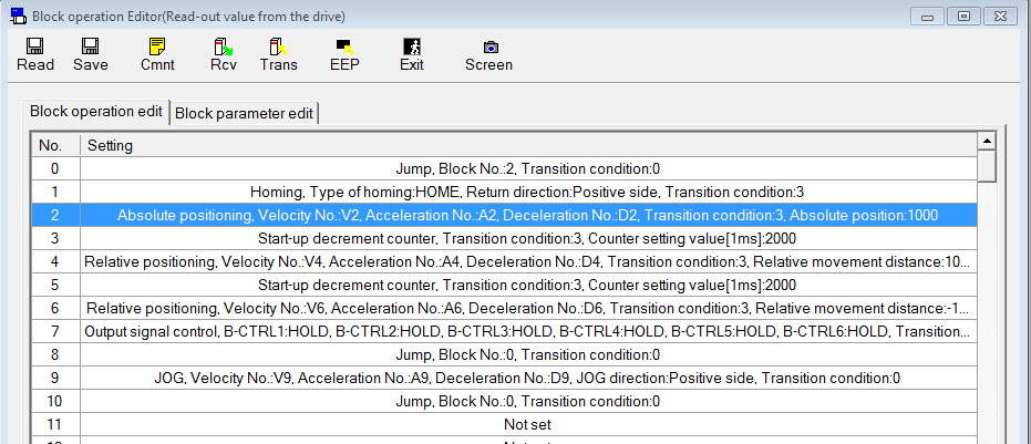
You can set the block commands using the PANATERM configuration software or by Modbus commands if you are using a PLC with a Modbus RTU port. The block commands are either started by digital signals from a PLC (e.g. STB, B-SEL1 to B-SEL128), a trigger switch, or by Modbus commands.
This Quick Start Guide explains how to wire and configure the servo driver for block operation using Modbus commands.
Example
An FP0H PLC and a MINAS A6SF servo driver are connected to control the driver by Modbus commands.

Wiring
Recommendations for wiring
It is the customer's responsibility to apply the countermeasures that they consider necessary to comply with current regulations on wiring, safety and reducing EMI.
Do not forget to meet the specifications indicated in the hardware manual for each of the devices being wired. If any specifications in the manual conflict with the information in this document, the manufacturer's manual takes preference.
For detailed information on reducing EMI, please refer to Recommendations for EMC-compliant wiring of servo drivers and motors.
Connectors of the servo driver
XA connector (main power connector)
Connect the power supply cable to the XA connector. For a 1-phase power supply of 230V, connect a 2-wire cable to the servo driver as illustrated. The L2 pin is not used in 1-phase mode.

XB connector (motor connector)
Connect the motor cable to the XB connector. The wires are labeled with the letters U, V, and W. Do not change the sequence of the motor phases, e.g. by connecting V to W.

X6 connector (encoder connector)
Connect the encoder cable to the X6 connector.

X2 connector (serial communication port)
Connect the serial communication cable DV0PM20024CAB to the X2 connector and to COM port 0 (RS232C port) of the FP0H PLC.

X1 connector (USB connector for PC connection)
The servo driver is configured using the PANATERM configuration software . Use a commercially available USB A to mini-B cable to connect the PC to the servo driver.

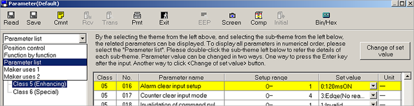
Make parameter settings in PANATERM
Use the PANATERM configuration software to configure the MINAS servo driver.
- Select the Parameter tab.
- Select the parameter list for your type of servo driver.
Basic parameters overview
The following table shows the setting range and description of the basic parameters.
Parameter |
Range |
Description |
|---|---|---|
Pr0.00 |
0 or 1 |
Motor rotation direction |
Pr0.01 |
0 to 6 |
Control mode |
Pr0.08 |
0 to 1048576 [pulse] (MINAS A5) 0 to 8388608 [pulse] (MINAS A6) |
Number of pulse signals per motor revolution |
Pr4.05 |
0 to 16777215 |
Function assignment for pin 29 of X4 connector |
Pr5.29 |
0 to 7 |
RS232C baud rate |
Pr5.30 |
0 to 7 |
RS485 baud rate |
Pr5.31 |
0 to 127 |
Axis number |
Pr5.37 |
0 to 2 |
Communication protocol |
Pr5.38 |
0 to 5 |
Modbus parity and stop bit setting |
Pr5.39 |
0 to 10000 |
Modbus response waiting time |
Pr6.28 |
0 to 2 |
Block operation mode |
Pr0.00 (Motor rotation direction)
PANATERM parameter: Rotational direction setting
Setting range: 0 or 1
The default value is 1: Rotation in CCW direction (counterclockwise direction).
Pr0.01 (Control mode)
PANATERM parameter: Control mode setting
Setting range: 0 to 6
The default value is 0: Position control
Select 0: Position control (block operation mode only supports position control)
Pr0.08 (Number of pulse signals per motor revolution)
PANATERM parameter: Command pulse number per one motor revolution
Setting range: 0 to 1048576 [pulse] (MINAS A5), 0 to 8388608 [pulse] (MINAS A6)
The default value is 10000 pulses per motor revolution.
Pr4.05 (Function assignment for pin 29 of X4 connector)
PANATERM parameter: SI6 input selection
Setting range: 0 to 16777215
The default value is 197379: servo-on input
Select 0 to disable the default pin assignment.
Pr5.29 (RS232C baud rate)
Set this parameter if the servo driver is connected via RS232C.
PANATERM parameter: RS232 communication baud rate setting
Setting range: 0 to 7 (2400 to 230400bit/s)
The default value is 2 (9600bit/s).
Make sure the baud rate setting in the PLC program and in the servo driver are identical. In this example, select 6: 115200bit/s.
Pr5.30 (RS485 baud rate)
Set this parameter if the servo driver is connected via RS485.
PANATERM parameter: RS485 communication baud rate setting
Setting range: 0 to 7 (2400 to 230400bit/s)
The default value is 2 (9600bit/s).
Make sure the baud rate setting in the PLC program and in the servo driver are identical. In this example, select 6: 115200bit/s.
Pr5.31 (Axis number)
PANATERM parameter: Axis number
Setting range: 0 to 127
The default value is 1.
Select a value between 1 and 127. 0 is not accepted with Modbus RTU. Make sure the axis number setting in the PLC program and in the servo driver are identical. In this example, set axis 1.
Pr5.37 (Communication protocol)
PANATERM parameter: Modbus connection setting
Setting range: 0 to 2
The default value is 0 (MINAS standard protocol).
Select 1: Modbus-RTU (RS232 communication) or 2: (RS485 communication), depending on your requirements.
Pr5.38 (Modbus parity and stop bit setting)
PANATERM parameter: Modbus communication setting
Setting range: 0 to 5
The default value is 0: Even/1 bit
Make sure the parity and stop bit setting in the PLC program and in the servo driver are identical.
In this example, select “Odd/1 bit”.
Pr5.39 (Modbus response waiting time)
PANATERM parameter: Modbus response waiting time
Setting range: 0 to 10000
The default value is 0.
Set 5ms for the FP0H. (If you are using a different PLC type, set 0ms for the FP7 and 50ms for the FP-X or FPS).
Pr6.28 (Block operation mode)
PANATERM parameter: Special function selection
Setting range: 0 to 1
The default value is 0.
Select 1: Block operation valid (Modbus)
Function test
To quickly test your settings, use one of the demo programs included in our programming library MC_Modbus_Library
|
|
|---|---|
|
Conduct trial runs of the servo motor only with the motor shaft disconnected from the machine to avoid any accident. |


- Double-click the POU _999_Sample_MoveRelative in the navigator.
The POU opens in the programing window:
POU _999_Sample_MoveRelative of MC_Modbus_Library in Control FPWIN Pro 7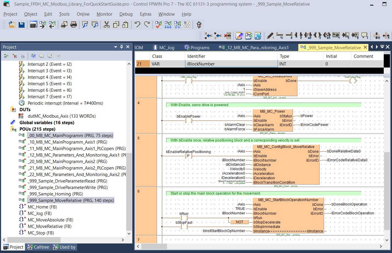
This program performs a relative movement on axis 1. Make sure the same axis is set in PANATERM.