Position control in EtherCAT networks
Before you start
Before operating this product, read the safety instructions in the related Operating Instructions.
This product is for industrial use only.
Electrical connections must be made by qualified electrical personnel.
About this document
Step-by-step instructions will guide you through connecting an FP7 EtherCAT unit to a MINAS servo driver.
Available software
The following software is available free of charge.
-
This link will take you to the Panasonic Industry Co., Ltd. Web site.
Control Motion Integrator tool
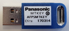
You can download a trial version. A dongle is required after the 60-day trial period.
Control FPWIN Pro7 programming software (basic version)
-
This programming library was developed for the FP7 EtherCAT unit and offers convenient functions and function blocks for basic positioning tasks.
Functional overview
Position control is a control mode in which the motor moves the load to a specified target position.
The servo driver can be controlled via EtherCAT from any host controller which supports EtherCAT communication. This Quick Start Guide explains how to wire and configure the servo driver and the host controller to get your system up and running.
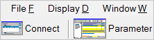
Use the Control Motion Integrator tool to configure the FP7 EtherCAT unit.
Example
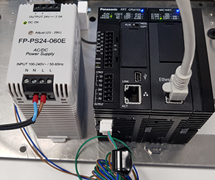
The host controller is an FP7 EtherCAT unit. It is connected to a MINAS A6B servo driver by an EtherCAT cable.

- (1) MINAS A6B servo driver
- (2) Load to be moved
- (3) 24V DC power supply
- (4) EtherCAT cable
- (5) FP7 PLC and EtherCAT unit
Wiring
Recommendations for wiring
It is the customer's responsibility to apply the countermeasures that they consider necessary to comply with current regulations on wiring, safety and reducing EMI.
Do not forget to meet the specifications indicated in the hardware manual for each of the devices being wired. If any specifications in the manual conflict with the information in this document, the manufacturer's manual takes preference.
For detailed information on reducing EMI, please refer to Recommendations for EMC-compliant wiring of servo drivers and motors.
Connectors of the servo driver
XA connector (main power connector)
Connect the power supply cable to the XA connector. For a 1-phase power supply of 230V, connect a 2-wire cable to the servo driver as illustrated. The L2 pin is not used in 1-phase mode.

XB connector (motor connector)
Connect the motor cable to the XB connector. The wires are labeled with the letters U, V, and W. Do not change the sequence of the motor phases, e.g. by connecting V to W.

X6 connector (encoder connector)
Connect the encoder cable to the X6 connector.

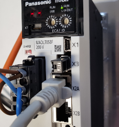
X1 connector (USB connector for PC connection)
The servo driver is configured using the PANATERM configuration software . Use a commercially available USB A to mini-B cable to connect the PC to the servo driver.

X2A connector (EtherCAT connector)
Connect an Ethernet cable to the X2A connector of the MINAS A6B servo driver and to the EtherCAT port of the FP7 EtherCAT unit.
Connect the FP7 EtherCAT unit to a 24V DC power supply.
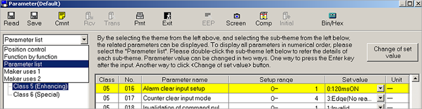
Make parameter settings in PANATERM
Use the PANATERM configuration software to configure the MINAS servo driver.
- Select the Parameter tab.
- Select the parameter list for your type of servo driver.
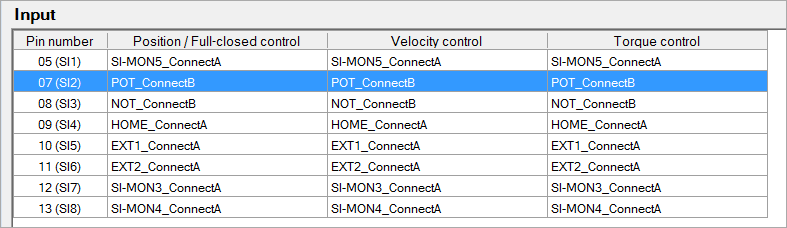
Make pin assignments in PANATERM
If you use an FP7 EtherCAT unit, the POT and NOT limit switch inputs cannot be assigned to pin 07 and 08. (If you need these limit switches, refer to the FP7 Motion Control Unit User's Manual.)
- Select .

The current pin assignment is uploaded from the servo driver.
- Double-click on the lines of pin number 07 (SI2) and 08 (SI3).
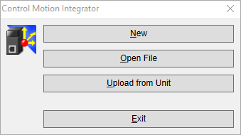
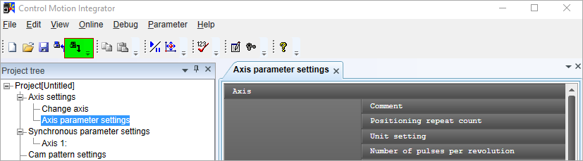
Make parameter settings in Control Motion Integrator
Use the Control Motion Integrator tool to configure the FP7 EtherCAT unit. The software can be started as a stand-alone product or from within the Control FPWIN Pro 7 programming software. In this procedure, we assume that you are using the stand-alone version. For details on the procedure in Control FPWIN Pro 7, refer to the online help of the programming library MC_EtherCAT_Library.
If the trial period of 60 days for the Control Motion Integrator tool has expired, you must connect a hardware dongle to your PC to be able to change the EtherCAT communication settings.
- Select New.
- Select the unit and the number of connected axes. In our example, it is one axis only.
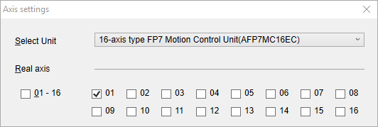
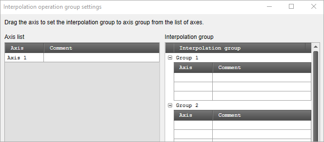
- In this example, we do not use interpolation because there is only one axis. Select OK.
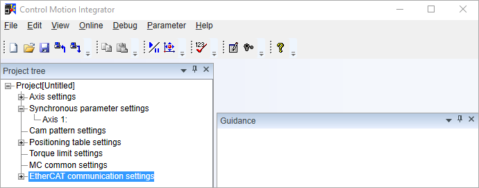
- Double-click on EtherCAT communication settings to search for connected axes.
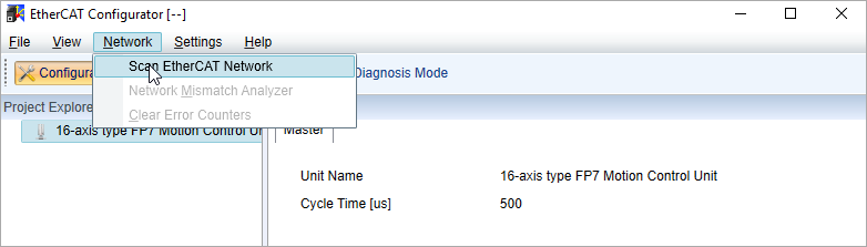
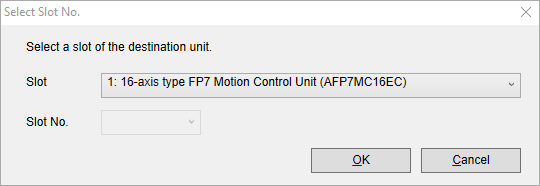
- Select .
- Select the number of the slot where you have physically installed the FP7 EtherCAT unit and select OK.
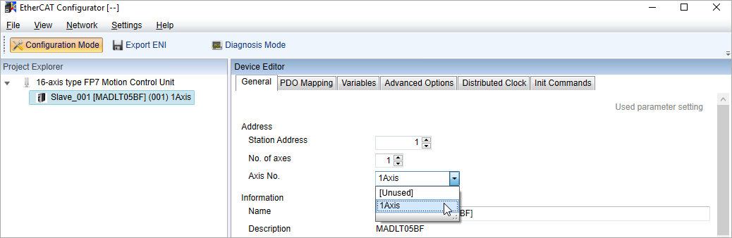
- The connected axis is displayed in the Project Explorer. Select the axis number of the corresponding station number. Then close the window.
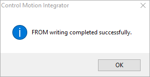
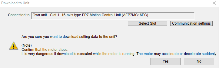
- Download the configuration by selecting the green highlighted button.
- Select the number of the slot where you have physically installed the FP7 EtherCAT unit and select Yes.
- Select OK to complete the process.