PANATERM – Real-time auto-gain tuning
Before you start
Before operating this product, read the safety instructions in the related Operating Instructions.
This product is for industrial use only.
Electrical connections must be made by qualified electrical personnel.
About this document
Step-by-step instructions will guide you through a real-time auto-gain tuning procedure for a MINAS servo driver. The auto-tuning is performed with the PANATERM configuration software.
Available software
The following software is available free of charge.
-
This link will take you to the Panasonic Industry Co., Ltd. Web site.
Functional overview
Auto-tuning is required for all applications to adjust the servo motor to the specific mechanical conditions. You can choose one of the following auto-tuning functions:
Fit-gain tuning
Real-time auto-gain tuning
This Quick Start Guide explains how to perform real-time auto-gain tuning.
While the fit-gain tuning function guides you through an automatic fine-tuning process, real-time auto-gain tuning mainly adjusts the rigidity of the machine. If you are using a MINAS A6 servo driver, first try fit-gain tuning. If fit-gain tuning was not successful, perform real-time auto-gain tuning. Both methods can be executed using PANATERM.
If possible, you should perform real-time auto gain-tuning on the machine with the servo motor and the mechanical loads connected and with the actual movements.
Usually, auto-tuning has the following goals:
Reduce the settling time to reduce cycle times.
Reduce mechanical vibration to increase the life time of the machine.
Reduce overshoot and undershoot to reach the target position within the allowed hysteresis.
Decrease the response time to reach the target position faster.
Overshoot, undershoot, and settling time of the position value
Example
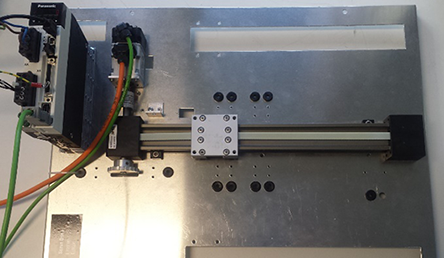
A MINAS A6SF servo driver is connected to a servo motor, which is coupled to a belt. The control mode is position control. A continuous movement within the mechanical limits, no mechanical vibration, no overshoot or undershoot, and a reduced settling time are required.
Wiring
Recommendations for wiring
It is the customer's responsibility to apply the countermeasures that they consider necessary to comply with current regulations on wiring, safety and reducing EMI.
Do not forget to meet the specifications indicated in the hardware manual for each of the devices being wired. If any specifications in the manual conflict with the information in this document, the manufacturer's manual takes preference.
For detailed information on reducing EMI, please refer to Recommendations for EMC-compliant wiring of servo drivers and motors.
Connectors of the servo driver
XA connector (main power connector)
Connect the power supply cable to the XA connector. For a 1-phase power supply of 230V, connect a 2-wire cable to the servo driver as illustrated. The L2 pin is not used in 1-phase mode.

XB connector (motor connector)
Connect the motor cable to the XB connector. The wires are labeled with the letters U, V, and W. Do not change the sequence of the motor phases, e.g. by connecting V to W.

X6 connector (encoder connector)
Connect the encoder cable to the X6 connector.

X1 connector (USB connector for PC connection)
The servo driver is configured using the PANATERM configuration software . Use a commercially available USB A to mini-B cable to connect the PC to the servo driver.

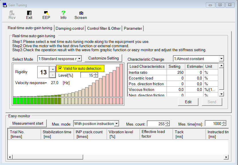
Perform real-time auto-gain tuning
Use the PANATERM configuration software to perform auto-tuning.
- While the motor is performing a repetitive, constant movement, select the Tuning tab.

- (1) Tuning tab
- Select the Damping control tab.

- (1) Damping control tab
- Select the Valid for auto detection check box.