Position control with SIMATIC S7-1200 host controller over Modbus RTU
Before you start
Before operating this product, read the safety instructions in the related Operating Instructions. This product is for industrial use only. Electrical connections must be made by qualified electrical personnel.
Related documents
Technical Reference - Modbus communication and block operation specification (SX-DSV03042) for MINAS A6. This manual can be downloaded from the Panasonic Industry Co., Ltd. Web site
 .
.SIMATIC S7-1200 Programmable controller System Manual.
Configuration

In this example, a SIMATIC S7-2100 PLC is connected to a MINAS A6SF servo driver via Modbus RTU.
A communication board for the PLC is required for the communication, as the CPU does not include Modbus RTU communication as standard.
Use a dedicated communication cable for the RS485 connection to the communication board.
The following hardware and software are used in this example:
Devices:
MINAS A6SF series servo driver and motor
SIMATIC S7-1200 PLC (6ES7-212-1BE40-0XB0), firmware version 4.7.0
SIMATIC S7-1200 communication board CB 1241, RS-485 (6ES7-241-1CH30-1XB0)
Cable:
RS485/RS232 communication cable for MINAS A6 (X2), 8-pin, 2m QUAE0002071 (DV0PM20024CAB)
Software:
STEP 7 (TIA Portal) V17
PANATERM set-up support software (available free of charge)
Wiring
Recommendations for wiring
It is the customer's responsibility to apply the countermeasures that they consider necessary to comply with current regulations on wiring, safety and reducing EMI.
Do not forget to meet the specifications indicated in the hardware manual for each of the devices being wired. If any specifications in the manual conflict with the information in this document, the manufacturer's manual takes preference.
For detailed information on reducing EMI, please refer to Recommendations for EMC-compliant wiring of servo drivers and motors.
Connect the servo driver
XA connector (main power connector)
Connect the power supply cable to the XA connector. For a 1-phase power supply of 230V, connect a 2-wire cable to the servo driver as illustrated. The L2 pin is not used in 1-phase mode.

XB connector (motor connector)
Connect the motor cable to the XB connector. The wires are labeled with the letters U, V, and W. Do not change the sequence of the motor phases, e.g. by connecting V to W.

X6 connector (encoder connector)
Connect the encoder cable to the X6 connector.

X2 connector (serial communication port)
Connect the serial communication cable QUAE0002071 (DV0PM20024CAB020) to the X2 connector and to the communication board of the S7-1200 PLC.


Make the following connections:
TA must be connected with T/RA, and TB with T/RB.
The TA-T/RA jumper must be connected to the negative terminal of the servo driver.
The TB-T/RB jumper must be connected to the positive terminal of the servo driver.
The GND connection with M is not required.
X1 connector (USB connector for PC connection)
The servo driver is configured using the PANATERM configuration software . Use a commercially available USB A to mini-B cable to connect the PC to the servo driver.

Make parameter settings in PANATERM
Use the PANATERM configuration software to configure the MINAS servo driver.
- Select the Parameter tab.
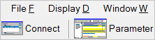
- Select the parameter list for your type of servo driver.
Basic parameters overview
The following table shows the setting range and description of the basic parameters.
Parameter |
Range |
Description |
|---|---|---|
Pr0.00 |
0 or 1 |
Motor rotation direction |
Pr0.01 |
0 to 6 |
Control mode |
Pr0.08 |
0 to 1048576 [pulse] (MINAS A5) 0 to 8388608 [pulse] (MINAS A6) |
Number of pulse signals per motor revolution |
Pr4.05 |
0 to 16777215 |
Function assignment for pin 29 of X4 connector |
Pr5.29 |
0 to 7 |
RS232C baud rate |
Pr5.30 |
0 to 7 |
RS485 baud rate |
Pr5.31 |
0 to 127 |
Axis number |
Pr5.37 |
0 to 2 |
Communication protocol |
Pr5.38 |
0 to 5 |
Modbus parity and stop bit setting |
Pr5.39 |
0 to 10000 |
Modbus response waiting time |
Pr6.28 |
0 to 2 |
Block operation mode |
Pr0.00 (Motor rotation direction)
PANATERM parameter: Rotational direction setting
Setting range: 0 or 1
The default value is 1: Rotation in CCW direction (counterclockwise direction).
Pr0.01 (Control mode)
PANATERM parameter: Control mode setting
Setting range: 0 to 6
The default value is 0: Position control
Select 0: Position control (block operation mode only supports position control)
Pr0.08 (Number of pulse signals per motor revolution)
PANATERM parameter: Command pulse number per one motor revolution
Setting range: 0 to 8388608 [pulse]
The default value is 10000 pulses per motor revolution.
Pr4.05 (Function assignment for pin 29 of X4 connector)
PANATERM parameter: SI6 input selection
Setting range: 0 to 16777215
The default value is 197379: servo-on input
Select 0 to disable the default pin assignment.
Pr5.30 (RS485 baud rate)
Set this parameter if the servo driver is connected via RS485.
PANATERM parameter: RS485 communication baud rate setting
Setting range: 0 to 7 (2400 to 230400bit/s)
The default value is 2 (9600bit/s).
Make sure the baud rate setting in the PLC program and in the servo driver are identical.
Pr5.31 (Axis number)
PANATERM parameter: Axis number
Setting range: 0 to 127
The default value is 1.
Select a value between 1 and 127. 0 is not accepted with Modbus RTU. Make sure the axis number setting in the PLC program and in the servo driver are identical.
Pr5.37 (Communication protocol)
PANATERM parameter: Modbus connection setting
Setting range: 0 to 2
The default value is 0 (MINAS standard protocol).
Select 2: Modbus-RTU (RS485 communication).
Pr5.38 (Modbus parity and stop bit setting)
PANATERM parameter: Modbus communication setting
Setting range: 0 to 5
The default value is 0: Even/1 bit
Make sure the parity and stop bit setting in the PLC program and in the servo driver are identical.
Pr5.39 (Modbus response waiting time)
PANATERM parameter: Modbus response waiting time
Setting range: 0 to 10000
The default value is 0.
Pr6.28 (Block operation mode)
PANATERM parameter: Special function selection
Setting range: 0 to 1
The default value is 0.
Select 1: Block operation valid (Modbus)
Set up the host controller
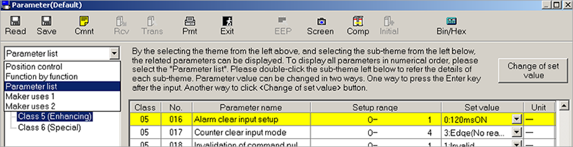
Create a new project in TIA Portal
When you create a new project in TIA Portal, select the PLC to be used, add the communication board, and set the IP address.
- Select the PLC type.
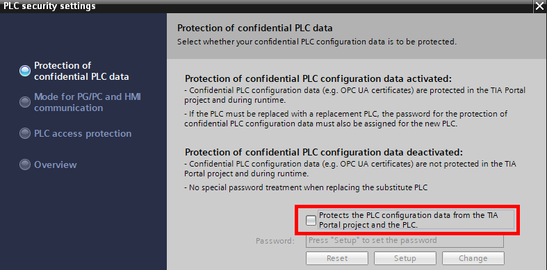
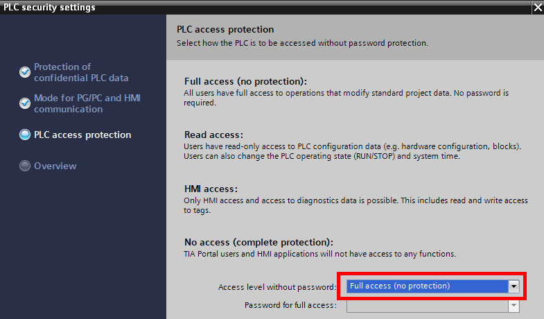
- Specify the security settings. In this example, no password is set.
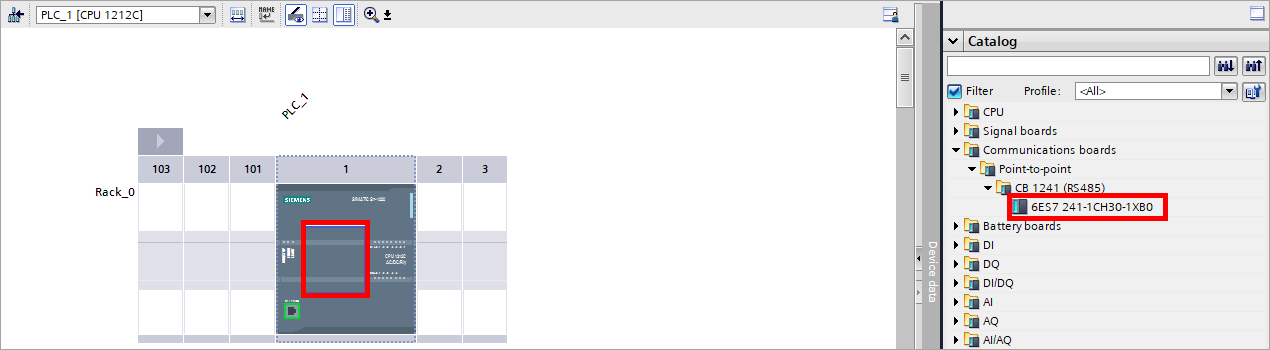
- Add the communication board that is needed for Modbus RTU communication.
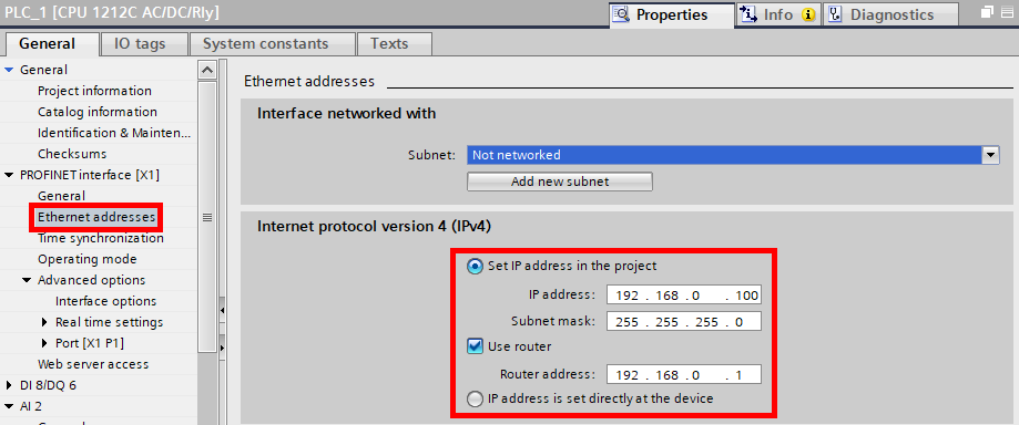
- Set the IP address of the PLC. The PLC should be in the same network as the PC.
Create a PLC program
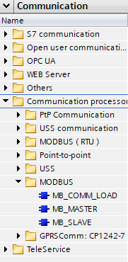
In the Communication task card, display the MODBUS instructions in the Communication processor block. Add MB_COMM_LOAD and MB_MASTER to the Main program block.
MB_COMM_LOAD
Use the MB_COMM_LOAD instruction to configure the port on the Modbus RTU communication board.
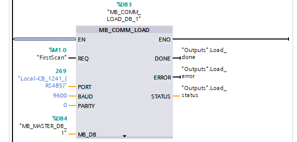
Input
- EN
Enables the instruction.
- REQ
A rising edge starts the operation. It is recommended to allow edge detection on the first cycle (FirstScan tag).
- PORT
Set the communication port.
- BAUD
Set the communication baud rate. It must match the setting of Pr.5.30 in the PANATERM configuration software.
Values:- 300, 600, 1200, 2400, 4800, 9600, 19200, 38400, 57600, 76800, 115200
- PARITY
Set the communication parity. It must match the setting of Pr.5.38 in the PANATERM configuration software.
Values:- 0: None
- 1: Odd
- 2: Even
- MB_DB
Set the name of the MB_MASTER instruction.
Output
- ENO
TRUE if the function is executed without error.
- DONE
TRUE for one scan after the last request was completed with no error.
- ERROR
TRUE for one scan after the last request was terminated with an error.
- STATUS
Returns the error code.
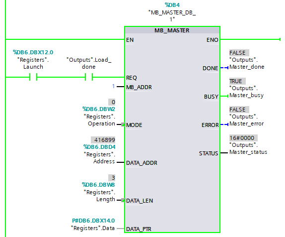
MB_MASTER
Use the MB_MASTER instruction to transmit data to the Modbus RTU slave.
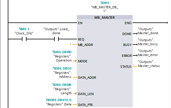
Input
- EN
Enables the instruction.
- REQ
Set the conditions for data transmission to the Modbus RTU slave. In this example, the configuration instruction MB_COMM_LD is executed every 0.5s.
- MB_ADDR
Set the slave ID. It must match the setting of Pr.5.31 in the PANATERM configuration software.
- MODE
Set the operation type.
Values:- 0: Read
- 1: Write
- DATA_ADDR
Set the starting address of the data to be accessed in the slave. See the Modbus functions table for valid addresses.
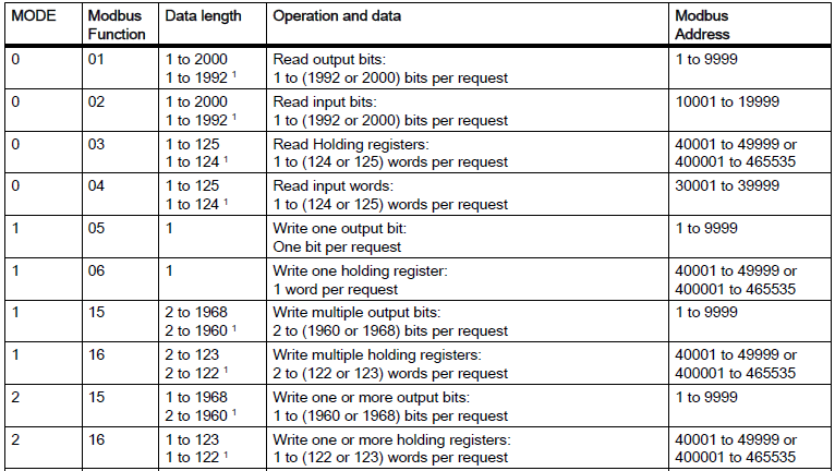
Source: S7-1200 Programmable controller, System Manual, V4.4 11/2019, A5E02486680-AN
NOTEYou must add 1 to the Modbus address given in the Technical Reference - Modbus communication and block operation specification (SX-DSV03042).- DATA_LEN
Set the number of bits or words to be accessed. See the Modbus functions table for valid lengths.
- DATA_PTR
Points to the variable that receives the data to be read or sets the data to be written. Use an array to read or write multiple registers.
Output
- ENO
TRUE if the function is executed without error.
- DONE
TRUE for one scan after the last request was completed with no error.
- BUSY
- Values:
- 0: No operation in progress
- 1: Operation in progress
- ERROR
TRUE for one scan after the last request was terminated with an error.
- STATUS
Returns the error code.
Programming examples
Set Servo ON - Servo OFF
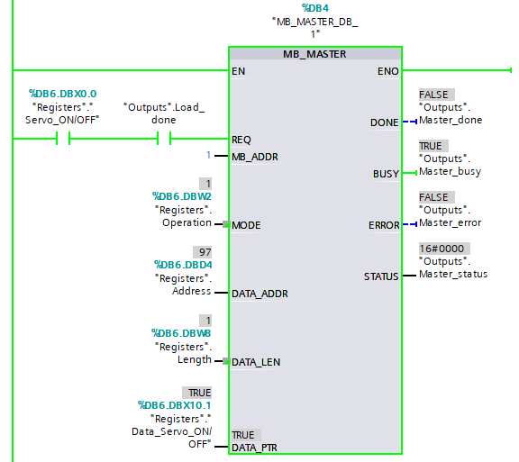
To send a servo ON request signal to the servo driver, set the Modbus address of the SERV-ON operation at DATA_ADDR and turn DATA_PTR to TRUE.
To send a servo OFF request, turn DATA_PTR to FALSE.
You must add 1 to the Modbus address given in the Technical Reference - Modbus communication and block operation specification (SX-DSV03042).
In this example, set 97 (0060h = 96) for DATA_ADDR.
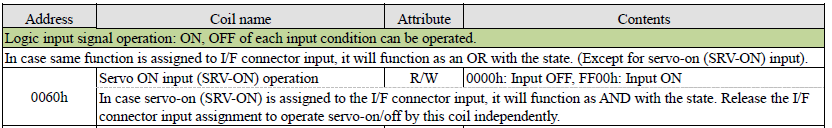
Source: Technical Reference - Modbus communication and block operation specification (SX-DSV03042)
Set a block command number
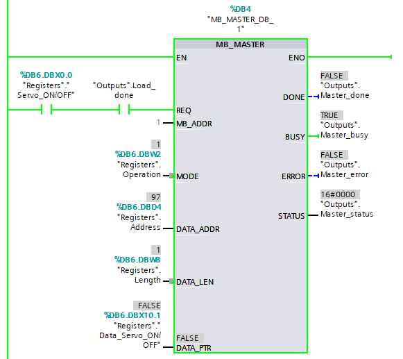
To execute a block command, set the Modbus address for block numbers at DATA_ADDR and set the block command number at DATA_PTR. In this example, we will set block command number 5.
You must add 1 to the Modbus address given in the Technical Reference - Modbus communication and block operation specification (SX-DSV03042). The Modbus address is preceded by the function code 4.
In this example, set 417429 (4202h = 17428, function code = 4) for DATA_ADDR.

Source: Technical Reference - Modbus communication and block operation specification (SX-DSV03042)
Read the encoder position
To read the encoder position, set the Modbus address for single-turn or multi-turn operations at DATA_ADDR. DATA_PTR points to the data bytes of the position value.
You must add 1 to the Modbus address given in the Technical Reference - Modbus communication and block operation specification (SX-DSV03042). The Modbus address is preceded by the function code 4.
In this example, set 416899 (4202h = 16898, function code = 4) for DATA_ADDR.

Source: Technical Reference - Modbus communication and block operation specification (SX-DSV03042)