The compiler must designate a memory area to each variable which has not been directly assigned to a physical address.
Use to define the memory areas which are hold or non-hold and for these you can define the memory areas which are reserved for the system (compiler) and for the user. Adjust the memory areas by moving the sliders or by double-clicking the sliders.
The memory areas include:
-
Flag words WR,
-
Data registers DT and
-
File registers FL, depending on the PLC type used
For detailed information, refer to address definition.
With Maximize system areas according to the global variables, you provide maximum address areas to the system (compiler) automatically. The user area (area which is defined by variables entered by the user) is restricted to the areas which were allocated by global variables with explicit addresses.
Do not use explicit addresses in the editor's bodies, because they will be unaccounted for if you select Maximize system areas according to the global variables.
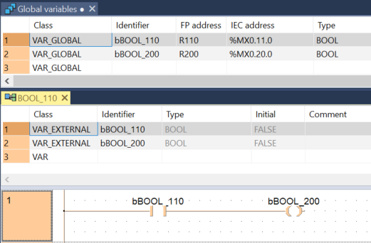
For example, if you use R110 and R200 directly in the body, WR11 and WR20 would not be taken into consideration.

WR11 and WR20 are taken into consideration when you use global variables with explicit addresses as shown in the following example:

Values in the non-hold area are lost in the event of a power cut or when switching from RUN to PROG mode; values in the hold area are retained. They are not initialized until the program is downloaded to the PLC.
If under , you activated Initialize all variables except global retain variables with explicit addresses, variables for which the user assigned addresses are not reinitialized.
-
For FP2, FP3, FP-C and FP5 the size of the file register (FL) can be set in the Project pane under .
-
The address from which the areas are self-holding can be set in the Project pane under .
-
When you change the compiler options, you must recompile the entire project.
-
Each variable which did not receive an address in the global variable list is automatically assigned a memory area by the compiler.
-
Not all memory areas apply for all PLC types (highlighted in light gray).
- Do not assign addresses unless you have to! Provide addresses for PLC inputs and outputs (X, Y) or if access to certain memory areas is required.
- The compiler automatically assigns addresses after the power has been turned on. This prevents errors caused by duplicate outputs and ensures that the addresses are automatically updated when the PLC type is changed.
The following table shows where the compiler allocates variables of a given class and data type:
|
Class |
Data type |
Memory area |
|---|---|---|
|
VAR, VAR_GLOBAL |
BOOL |
Flag words WR, non-hold |
|
VAR_RETAIN, VAR_GLOBAL_RETAIN |
BOOL |
Flag words WR, hold |
|
VAR, VAR_GLOBAL |
INT, DINT, WORD, DWORD, TIME, REAL, STRING |
Data register DT, non-hold File register FL, non-hold |
|
VAR_RETAIN, VAR_GLOBAL_RETAIN |
INT, DINT, WORD, DWORD, TIME, REAL, STRING |
Data register DT, hold File register FL, hold |
The compiler also automatically creates labels which are required for loops.
The number of labels for the system (compiler) can be specified using .
To activate the standard settings for your compiler, select Default.