REAL
For FP-e and FP0 only: Do not use REAL instructions in interrupt programs.
Integer literals like '123' are implicitly converted to REAL.
Variables of the data type REAL are real 32 bit numbers based on IEEE754. The mantissa is 23 bits and the exponent is 8 bits.

- (1) Bit position
- (2) Sign bit: 0 positive, 1 negative
- (3) Exponents (8-bit)
- (4) Mantissa (23-bit)
Range for REAL values: |
-3.402823466*E38 to -1.175494351*E-38 |
0.0 |
|
+1.175494351*E-38 to +3.402823466*E38 |
|
The default for the initial value, e.g. for the variable declaration in the POU header or in the global variable list: |
0.0 |
You can enter REAL values in the following format: [+-] Integer.Integer [(Ee) [+-] Integer]
5.983e-7
-33.876e12
3.876e3
0.000123
123.0
User function which checks whether a real number is valid
Problem:
Floating point instructions require valid real numbers.
Range for REAL values: |
-3.402823466*E38 to -1.175494351*E-38 |
0.0 |
|
+1.175494351*E-38 to +3.402823466*E38 |
If a real number is less than -3.402823466*E38, or greater than +3.402823466*E38 the system variables sys_bIsOperationErrorHold and sys_bIsOperationErrorNonHold are set and the operation is stopped if system register 26 is set to Stop.
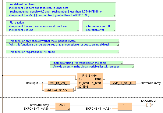
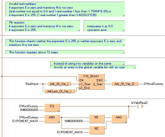
This condition is checked by the functions IsValidReal and IsValidReal2.
If a real number is in the range -1.175494351*E-38 to +1.175494351*E-38, the PLC assumes it is 0.0 and no error flags are set.
Some old PLC types like FP1 or FP-M do not support real numbers.
Example for IsValidReal
In this example the function IsValidReal and IsValidReal2 is programmed in ladder diagram (LD) and instruction list (IL). The same POU header is used for all programming languages.
POU header
In the POU header, all input and output variables are declared that are used for programming this function.

LD: IsValidReal

LD: IsValidReal2
