
The high-speed counter and pulse output instructions can be used with the following FP Series PLCs: FP0, FP-e, FPS, FP-X, FP0R.
Control FPWIN Pro offers two concepts for programming with high-speed counter instructions:
F instructions
Tool instructions
When should you use tool instructions instead of F instructions?
You want to develop universal function blocks for libraries.
You must program for different PLC types of the FP series.
You're tired of setting control code bits and looking up available channel numbers.
However, the F instructions may be easier to use for beginners or users familiar with FPWIN GR.
Most of the information, which is accessible via information and control functions, is stored in special internal flags and special data registers. These flags and registers can also be accessed using PLC-independent system variables.To take advantage of the features you prefer, the instructions of both libraries can be mixed.
When programming with the tool instructions, be sure to refer to the detailed information provided via the links to the related F instructions.
Main features |
F instructions | Tool instructions |
|---|---|---|
Pre version 6.4 support |
l |
|
Use of inline functions |
l |
|
Use of FPWIN GR function names |
l |
|
Less code with constant channel numbers |
l |
|
Control codes |
l |
|
Control functions |
l |
|
Information functions |
l |
|
Variable channel numbers |
l |
|
Universal functions for all PLCs |
l |
|
For use in universal user function blocks |
l |
|
Common channel configuration DUT for all PLCs and all pulse output instructions |
l |
| F instructions | Tool instructions | ||
 |
 |
||
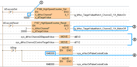
(1) |
Supports only constant channel numbers, in this example channel 2. |
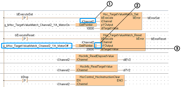
(1) |
Supports variable channel numbers, in this example channel 2. |
(2) |
Outputs with explicit user addresses in the Y area |
(2) |
Access to outputs with explicit user addresses via a pointer variable. This pointer variable can also be applied via inputs of user-defined function blocks. |
(3) |
System variables are used to read special data registers for channel 2. |
(3) |
The name of the output variable g_bHsc_TargetValueMatch_Channel2_ YA_MotorOff must follow a certain pattern, please refer to Hsc_TargetValueMatch_Set. |
(4) |
PLC-specific control code settings are required, e.g. for clearing a high-speed counter instruction |
||
Conclusion:
|
Conclusion:
|
||
Use the high-speed counter instructions to count input pulses from sensors or encoders, and to turn outputs to TRUE or FALSE once a specified target value has been reached.
When used with a motor driver, the pulse output instructions enable typical positioning operations such as trapezoidal control, home return, and JOG operation.
The number of channels for the built-in high-speed counter and for pulse output, the counting range, the input and output numbers, as well as performance specifications differ depending on the PLC type. For details, please refer to the corresponding hardware manual.
When using a high-speed counter instruction: Select the high-speed counter input for the desired channel in the system registers.
To specify the counter input mode, select the high-speed counter inputs in the system registers.
Input mode |
Input signals |
|
|---|---|---|
Incremental |
 |
|
Decremental |
 |
|
Two-phase |
Incremental counting  |
|
Decremental counting  |
||
Incremental/decremental |
 |
|
(a) |
Increasing |
|
(b) |
Decreasing |
|
Incremental/decremental control |
 |
|
(a) |
Increasing |
|
(b) |
Decreasing |
|
Count for reset (incremental) |
 |
|
(a) |
Rising edge: count disabled, elapsed value cleared |
|
(b) |
Falling edge: count enabled |
|
(c) |
Count prohibited |
|
The reset at (3) is executed by the interruption at (a) (rising edge) and (b) (falling edge).The reset input can be enabled/disabled using bit 2 of sys_wHscOrPulseControlCode. |
||
Control codes are used to perform special counter operations.
When programming with F instructions:
Use a MOVE instruction to write or read the control code to or from the special data register reserved for this code (DT90052 or DT9052, depending on the PLC type).The special data register where the high-speed counter and pulse output control code are stored can be accessed with the system variable sys_wHscOrPulseControlCode.
When programming with tool instructions:
Use universal high-speed counter control instructions and pulse output control instructions which apply to all PLC types to make control code settings. Use the high-speed counter information instructions and pulse output information instructions to monitor control code settings.
The elapsed value is stored as a double word in the special data registers.
When programming with F instructions:
Access the special data registers using the system variable sys_diHscChannelxElapsedValue (where x=channel number).
The channel number is an input parameter of the high-speed counter or pulse output instruction. Most of the other parameters, e.g. speed and target value, can be specified using predefined DUTs. These DUTs can be found in the FP Library.
When programming with tool instructions:
Use universal high-speed counter information and control instructions and pulse information and control instructions which apply to all PLC types to read and write the elapsed value.
The channel number and control code settings, e.g. CW/CCW, absolute or relative value control, or duty ratio are specified in a channel configuration DUT common to all PLC types. Other parameters, e.g. speed and target value can be applied directly to the instruction.
The high-speed counter and pulse output status is stored in special internal flags. To access the special internal flags, use the PLC-independent system variables.
When a high-speed counter instruction is executed, the high-speed counter control flag (e.g. sys_bIsHscChannel0ControlActive) for the channel used turns to TRUE. No other high-speed counter instruction using the same channel can be executed as long as the control flag is TRUE.
When a pulse output instruction is executed and pulses are being output, the pulse output control flag (e.g. sys_bIsPulseChannel0Active) of the corresponding channel is TRUE. No other pulse output instruction can be executed as long as this flag is TRUE.
FP-X, FP0R:
The high-speed counter control flag (e.g. sys_bIsHscChannel0ControlActive) and the pulse output control flag (e.g. sys_bIsPulseChannel0Active) are assigned to different special internal flags.
FP-Sigma, FP0, FP-e:
The high-speed counter control flag (e.g. sys_bIsHscChannel0ControlActive) and the pulse output control flag (e.g. sys_bIsPulseChannel0Active) are assigned to the same special internal flag number (e.g. R903A). Therefore, when a high-speed counter instruction or a pulse output instruction is executed, both the high-speed counter control flag (e.g. sys_bIsHscChannel0ControlActive) and the pulse output control flag (e.g. sys_bIsPulseChannel0Active) for the channel used are TRUE. No other high-speed counter instruction or pulse output instruction can be executed as long as this flag is TRUE. The status of the high-speed counter control flag or pulse output control flag may change while a scan is being carried out. For example, if the number of received bytes is read more than once different statuses may exist within one scan.
To access special data registers and special internal flags, use the PLC-independent system variables.