
The special data register where the high-speed counter and pulse output control code are stored can be accessed with the system variable sys_wHscOrPulseControlCode. (The system variable sys_wHscOrPulseControlCode corresponds to special data register DT90052.)
Operations performed by the pulse output control code:
To decelerate movement when near the home position, designate a near home input and set bit 4 of the special data register storing the pulse output control code (sys_wHscOrPulseControlCode) to TRUE and back to FALSE again.The near home bit is retained. Set this bit to FALSE right after setting it to TRUE to be able to set the near home input a second time during a home return.

By setting bit 3 of the data register storing the pulse output control code (sys_wHscOrPulseControlCode) to TRUE pulse output is stopped. The possibility of a forced stop should be provided for in every program using pulse output instructions. Reset bit 3 to FALSE to continue pulse output.

Pulse output
Elapsed value
1
When bit 1 of the control code is set to TRUE, counting is prohibited and the elapsed value keeps its current value. Counting is continued when bit 1 is reset to FALSE.

Pulse output
Elapsed value
Bit 0 of pulse output control code (software reset)
When bit 0 of the control code is set to TRUE, a software reset is performed and the elapsed value is set to 0. The elapsed value keeps the value 0 until bit 0 is reset to FALSE.
To cancel execution of a pulse output instruction, set bit 2 of the data register storing the pulse output control code (sys_wHscOrPulseControlCode) to TRUE. The pulse output control flag will then change to FALSE. To reenable execution of the instruction, reset bit 2 to FALSE.
Bits 0–15 of the control code are allocated in groups of four. The bit setting in each group is represented by a hex number (e.g. 00020000 0000 1001 = 16#2009).

Group |
(1) |
Channel number (channel n: 16#n) |
|
Group |
0 (fixed) |
||
Group |
(2) |
Near home input (bit 4) |
|
0: FALSE |
1: TRUE |
||
Group |
(3) |
Pulse output (bit 3) |
|
0: continue |
1: stop |
||
(4) |
0 (bit 2, fixed) |
||
(5) |
Count (bit 1) |
||
0: permit |
1: prohibit |
||
(6) |
Reset elapsed value to 0 (bit 0) |
||
0: no |
1: yes |
||
Example: 16#2009
Group |
Value |
Description |
|
|---|---|---|---|
|
2 |
Channel number: 2 |
|
|
0 |
(fixed) |
|
|
0 |
Near home input: FALSE |
|
|
9 |
Hex 9 corresponds to binary 1001 |
|
Pulse output: stop (bit 3) |
1 |
||
(bit 2, fixed) |
0 |
||
Count: permit (bit 1) |
0 |
||
Reset elapsed value to 0: yes (bit 0) |
1 |
||

Group |
(1) |
Channel number (channel n: 16#n) |
|
Group |
(2) |
1 (fixed) |
|
Group |
(3) |
Near home input (bit 4) (see note) |
|
0: FALSE |
1: TRUE |
||
Group |
(4) |
Pulse output (bit 3) |
|
0: continue |
1: stop |
||
(5) |
Count (bit 1) |
||
0: permit |
1: prohibit |
||
(6) |
Reset elapsed value to 0 (bit 0) |
||
0: no |
1: yes |
||
Example: 16#2109
Group |
Value |
Description |
|
|---|---|---|---|
|
2 |
Channel number: 2 |
|
|
1 |
(fixed) |
|
|
0 |
Near home input: FALSE |
|
|
9 |
Hex 9 corresponds to binary 1001 |
|
Pulse output: stop (bit 3) |
1 |
||
(Bit 2 fixed) |
0 |
||
Count: permit (bit 1) |
0 |
||
Reset elapsed value to 0: yes (bit 0) |
1 |
||
Bits 0–15 of the control code are allocated in groups of four. The bit setting in each group is represented by a hex number (e.g. 00020001 0000 1001 = 16#2109).

Group |
(1) |
Channel number (channel n: 16#n) |
|
Group |
1 (fixed) |
||
Group |
(2) |
Position control start request |
|
0: disabled |
1: enabled |
||
(3) |
Decelerated stop request |
||
0: disabled |
1: enabled |
||
(4) |
Near home input (bit 4) (see note) |
||
0: FALSE |
1: TRUE |
||
Group |
(5) |
Pulse output (bit 3) |
|
0: continue |
1: stop |
||
(6) |
Cancel pulse output control (bit 2) |
||
0: continue |
1: stop |
||
(7) |
Count (bit 1) |
||
0: permit |
1: prohibit |
||
(8) |
Reset elapsed value to 0 (bit 0) |
||
0: no |
1: yes |
||
Example: 16#2109
Group |
Value |
Description |
|
|---|---|---|---|
|
2 |
Channel number: 2 |
|
|
1 |
(fixed) |
|
|
0 |
Position control start request: disabled |
|
Decelerated stop request: disabled |
|||
Near home input: FALSE |
|||
|
9 |
Hex 9 corresponds to binary 1001 |
|
Pulse output: stop (bit 3) |
1 |
||
Cancel pulse output control (bit 2) |
0 |
||
Count: permit (bit 1) |
0 |
||
Reset elapsed value to 0: yes (bit 0) |
1 |
||
Bits 0–15 of the control code are allocated in groups of four, each group containing the settings for one channel. The bit setting in each group is represented by a hex number (e.g. 0000 0000 1001 0000 = 16#90).
Group |
|
|
Channel |
1 |
0 |

0: continue
1: stop
0: FALSE
1: TRUE
0: permit
1: prohibit
0: no
1: yes
Example: 16#90
Group |
Value |
Description |
|
|---|---|---|---|
|
9 |
Channel number: 1 Hex 9 corresponds to binary 1001 |
|
Pulse output: stop (bit 3) |
1 |
||
Near home input: FALSE (bit 2) |
0 |
||
Count: permit (bit 1) |
0 |
||
Reset elapsed value to 0: yes (bit 0) |
1 |
||
|
0 |
– |
|

All input and output variables used for programming this function have been declared in the POU header. The same POU header is used for all programming languages.
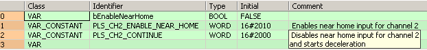
	VAR
	 bEnableNearHome: BOOL:=FALSE;
	END_VAR
	VAR CONSTANT
		PLS_CH2_ENABLE_NEAR_HOME: WORD:=16#2010;
			(*Enables near home input for channel 2*)
		PLS_CH2_CONTINUE: WORD:=16#2000;
			(*Disables near home input for channel 2
and starts deceleration*)
END_VARThe near home input is enabled for channel 2 during home return operations.
BODY
    WORKSPACE
        NETWORK_LIST_TYPE := NWTYPELD ;
        ACTIVE_NETWORK := 0 ;
    END_WORKSPACE
    NET_WORK
        NETWORK_TYPE := NWTYPELD ;
        NETWORK_LABEL :=  ;
        NETWORK_TITLE :=  ;
        NETWORK_HEIGHT := 8 ;
        NETWORK_BODY
B(B_VARIN,,PLS_CH2_ENABLE_NEAR_HOME,20,2,22,4,);
B(B_VARIN,,PLS_CH2_CONTINUE,20,6,22,8,);
B(B_F,E_MOVE!,Instance,22,0,28,4,,?DEN?D?AENO?C);
B(B_VAROUT,,sys_wHscOrPulseControlCode,28,2,30,4,);
B(B_F,E_MOVE!,Instance,22,4,28,8,,?DEN?D?AENO?C);
B(B_VAROUT,,sys_wHscOrPulseControlCode,28,6,30,8,);
B(B_CONTACT,,bEnableNearHome,4,1,6,3,R);
L(7,2,7,6);
L(1,2,4,2);
L(6,2,22,2);
L(7,6,22,6);
L(1,0,1,8);
        END_NETWORK_BODY
    END_NET_WORK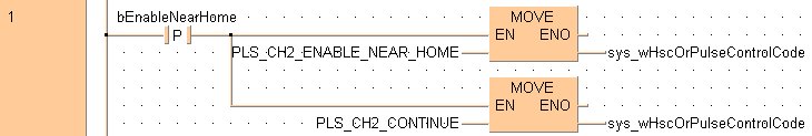
END_BODYif DF(bEnableNearHome) then
sys_wHscOrPulseControlCode:=PLS_CH2_ENABLE_NEAR_HOME;
sys_wHscOrPulseControlCode:=PLS_CH2_CONTINUE;
end_if;All input and output variables used for programming this function have been declared in the POU header.The same POU header is used for all programming languages.
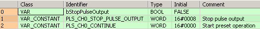
A forced stop of the pulse output is performed for channel 0.
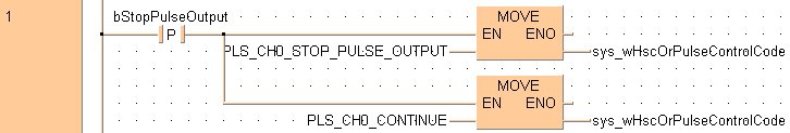
if DF(bStopPulseOutput) then
    sys_wHscOrPulseControlCode:=PLS_CH0_STOP_PULSE_OUTPUT;
    sys_wHscOrPulseControlCode:=PLS_CH0_CONTINUE;
end_if;Performing a forced stop may cause the elapsed value at the PLC output side to differ from the elapsed value at the motor input side. Therefore, you must execute a home return after pulse output has stopped.