Position control with Omron host controller over EtherCAT
Before you start
Before operating this product, read the safety instructions in the following manuals:
This product is for industrial use only.
Electrical connections must be made by qualified electrical personnel.
Description
Step-by-step instructions will guide you through connecting an Omron NX1P2 host controller to a MINAS A6 Multi servo drive system. You will also learn how to program a simple positioning task in Omron's Sysmac Studio software. Communication is achieved using EtherCAT.
Available software
The following software is available free of charge in our Panasonic Download Center.
The following software can be downloaded from Omron’s Web site (https://www.omron.eu./en/home):
Sysmac Studio software
Functional overview
A Panasonic MINAS A6 Multi servo drive system includes a power supply module, one or more 400V driver modules, and one or two motors connected to each driver module. Communication can be achieved through EtherCAT with any host controller that supports the CAN application protocol over EtherCAT (CoE).
Example
A servo drive system, consisting of a 15kW power supply module, an A-size 1.5kW two-axis driver module, and two servo motors with a rated power of 1.0kW and 1.5kW, is connected to an Omron NX1P2 host controller by an Ethernet cable to communicate via EtherCAT.
Use the following accessories:
1 x 400V AC power supply cable: Connects the MINAS A6 Multi power supply module to the main power supply (400V AC).
1 x 24V DC power supply cable: Connects the power supply unit (24V DC) and the host controller.
1 x grounding wire (M4 round terminal): Connects the PE terminals of the power supply module and the driver module.
2 x Panasonic motor cable: Connects the motor and the driver module.
2 x Panasonic encoder cable: Connects the encoder and the driver module.
1 x Ethernet cable: Connects the PC and the host controller.
1 x Ethernet cable (used for EtherCAT communication): Connects the host controller and the driver module.
1 x RJ11 communication cable (2 x RJ11 plug): Connects the power supply module and the driver module.
1 x feed bus bar (50mm) with end cap for the DC link bus (535V DC to 675V DC): Connects the power supply module and the driver module.
1 x feed bus bar (50mm) with end cap for the control bus (24V DC): Connects the power supply module and the driver module.

- (1) Power supply unit (24V DC)
- (2) Omron NX1P2 host controller
- (3) MINAS A6 Multi power supply module (400V AC, 15kW)
- (4) Two-axis MINAS A6 Multi driver module (1.5kW)
- (5) MINAS A6 servo motor B (1.5kW)
- (6) MINAS A6 servo motor A (1kW)
- (7) PC with Sysmac Studio
Wiring
Recommendations for wiring
It is the customer's responsibility to apply the countermeasures that they consider necessary to comply with current regulations on wiring, safety and reducing EMI.
Do not forget to meet the specifications indicated in the hardware manual for each of the devices being wired. If any specifications in the manual conflict with the information in this document, the manufacturer's manual takes preference.
For detailed information on reducing EMI, please refer to Recommendations for EMC-compliant wiring of servo drivers and motors.
Bottom side connectors of the servo drive system
The image shows the most important connectors of a power supply module (left) and a driver module (right). Please refer to the technical documentation for details about other connectors.

- (1)
X102: Main power supply (400V AC)
Connect the 400V AC main power supply cable to X102. Connect the PE terminals of the power supply module and the driver module by a grounding wire.
- (2)
X11: Control power supply (24V DC)
Connect the 24V DC control power supply to X11.
- (3)
X105A: Motor A, (4) X105B: Motor B
Connect the motor cable for servo motor A to X105A and the motor cable for servo motor B to X105B.
- (4)
X9A: Encoder A, (6) X9B: Encoder B
Connect the cable of encoder A to X9A and the cable of encoder B to X9B.
Top side connectors of the servo drive system
The image shows the most important connectors of a power supply module (left) and a driver module (right). Please refer to the technical documentation for details about other connectors.

- (1)
X1: Internal communication connector on power supply module, (2) X1A: Internal communication connector on driver module
Connect X1 and X1A with the RJ11 communication cable.
- (3)
X6A: EtherCAT communication connector on driver module
Connect an Ethernet cable between the EtherCAT connector of the host controller and X6A of the driver module.
Front side connectors of the servo drive system
The image shows the most important connectors of a power supply module (left) and a driver module (right). Please refer to the technical documentation for details about other connectors.

- (1)
X7: USB connector (for driver configuration) on driver module
The driver module is configured using the PC configuration software PANATERM. Use a commercially available USB A to mini-B cable to connect the PC to the driver module.
- (2)
X104: DC link bus connectors on power supply module and driver module (535V DC to 675V DC), (3) X12: Control bus (24V DC) connectors on power supply module and driver module
Attach the bus bars to X104 and X12 to connect the DC circuits of the power supply module and the driver module.
- (4)
Connectors for DC circuits without and with bus bars
Connectors of the Omron NX1P2 host controller
The image shows the front view of the host controller.

- (1)
24V DC power supply
Connect this connector to 24V DC.
- (2)
PORT1 EtherNet/IP connector
Connect an Ethernet cable between this connector and the Ethernet port of your PC.
- (3)
PORT2 EtherCAT connector
Connect an Ethernet cable between this connector and the X6A connector of the driver module.
Create a project in Sysmac Studio
Install Sysmac Studio on your PC
The servo drive system is controlled with Omron's Sysmac Studio software. Install this software and the Panasonic ESI file on your PC.
- Download the Sysmac Studio software from Omron’s website and execute the installation file.
- Copy the Panasonic ESI file (Panasonic_MINAS_A6Multi_V*.xml) to C:\Program Files (x86)\OMRON\Sysmac Studio\IODeviceProfiles\EsiFiles\ UserEsiFiles on your PC.
- Restart Sysmac Studio.
The download links can be found under Available software.
Create a new project in Sysmac Studio
Before you can connect your PC to the Omron NX1P2 host controller, you must create a new project in Sysmac Studio.
- Select the Sysmac Studio by icon on your desktop to start the software.
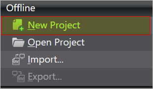
- On the Start Page, select New Project.
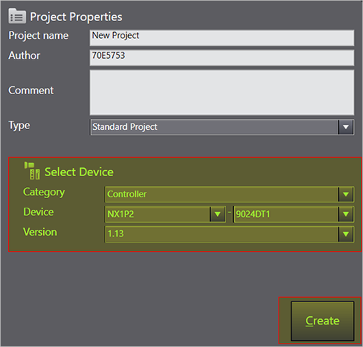
- Select the device and version number (see label of the host controller) and then Create.
- Select . Then double-click on the driver module to be connected.
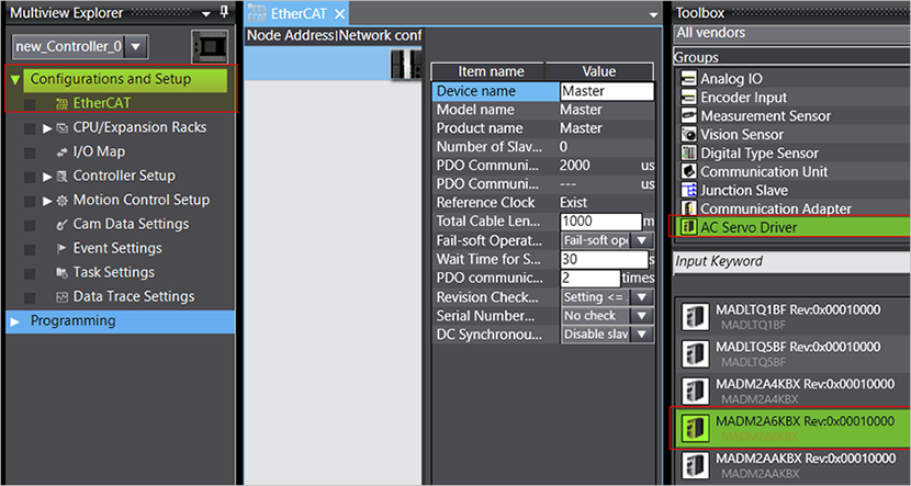 The driver module is now connected to the master (host controller).
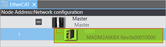
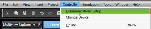
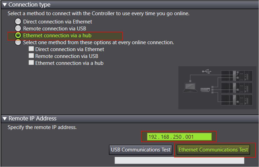
- Select to establish an Ethernet connection.
- Select the connection method Ethernet connection via a hub and enter the default IP address 192.168.250.001 for the host controller.Make sure your PC uses an IP address in the same subnet, e.g. 192.168.250.50.To check the communication, select Ethernet Communication Test. If Test OK is displayed, the communication is active.Select OK to save your settings.
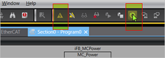
- Select the yellow triangle in the tool bar to go online.
 When the host controller is in RUN mode, the new status is displayed on the lower right.
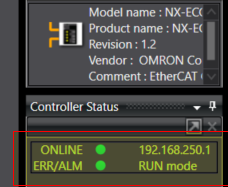
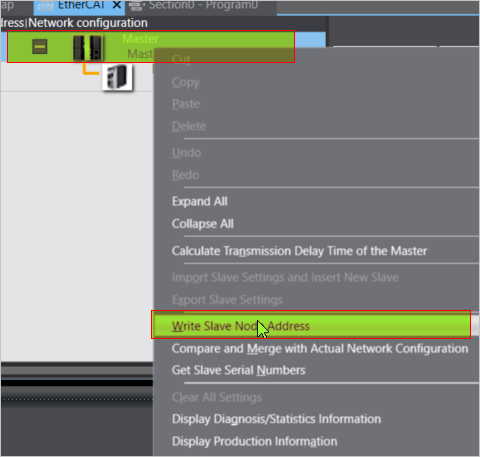
- Right-click on the master and select Write Slave Node Address to set the node address of the driver module.
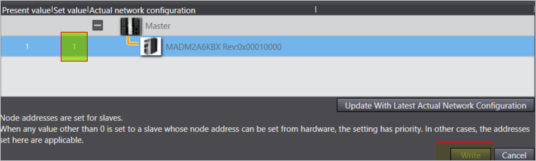
- Set a slave node address, e.g. 1, and select Write.
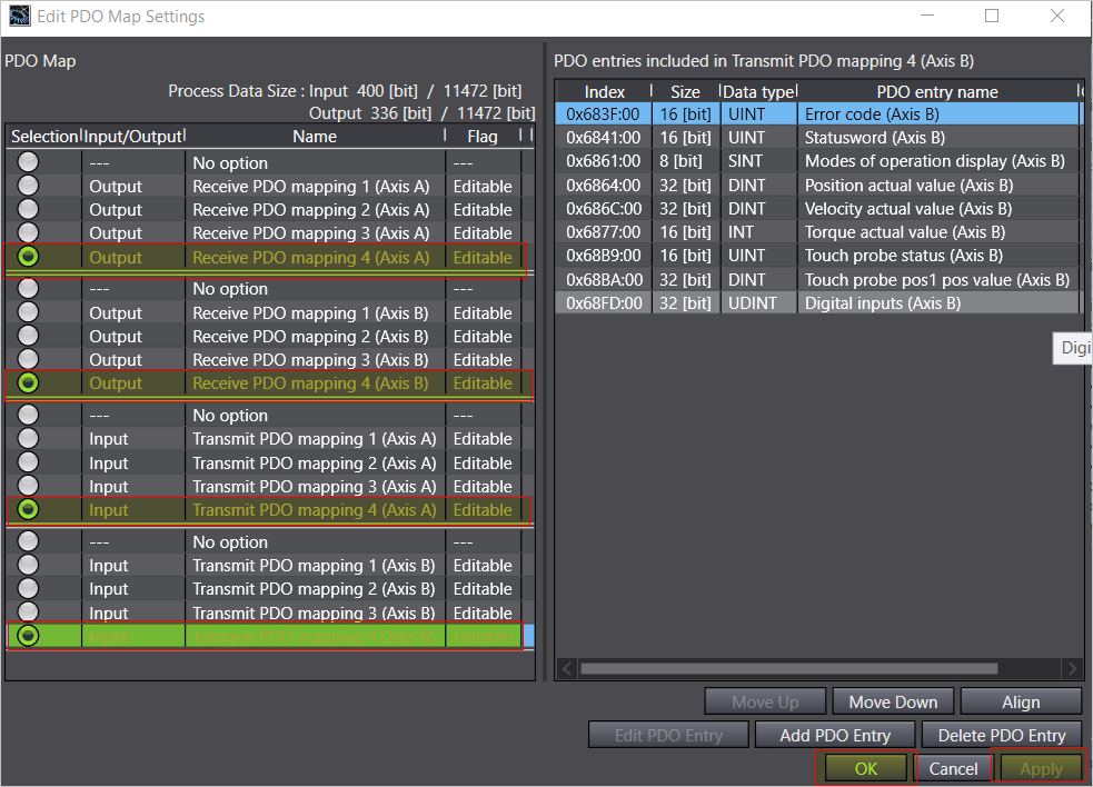
- After rebooting, stay in offline mode. Select the driver module and then Edit PDO Map Settings to select the PDO mappings for your application.
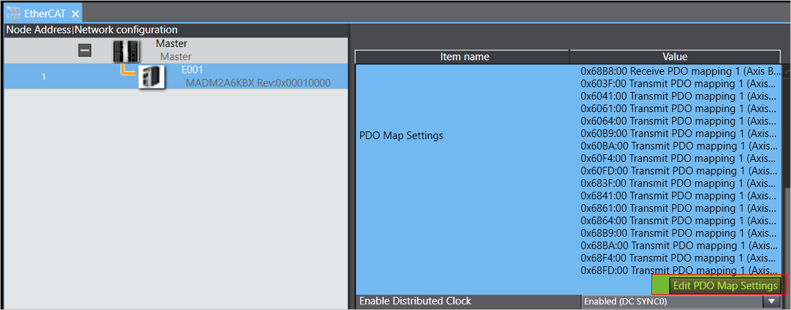
- For example, select PDO mapping 4 and then Apply and OK.
Axis configuration
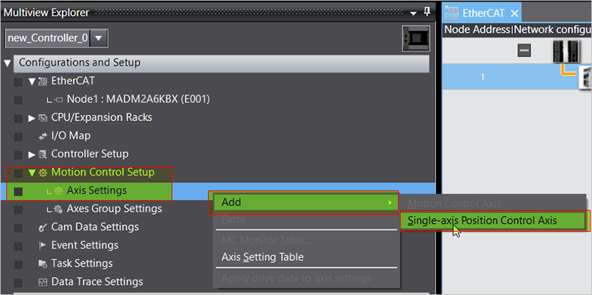
- Select to add an axis.
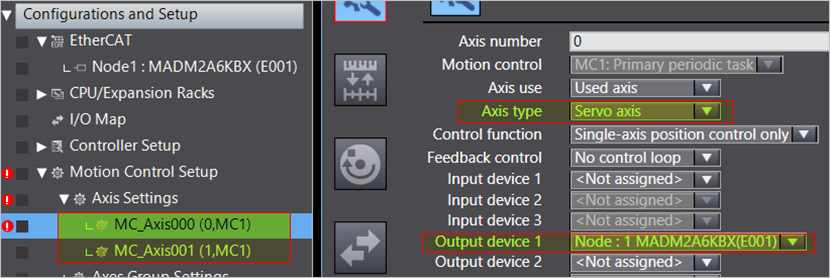
- For Axis type, select Servo axis and for Output device 1, select MADM2A6KBX(E001).
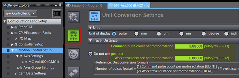
- Go to the Detailed Settings tab to make map the process data objects (PDO) to the NX1P2 variables.
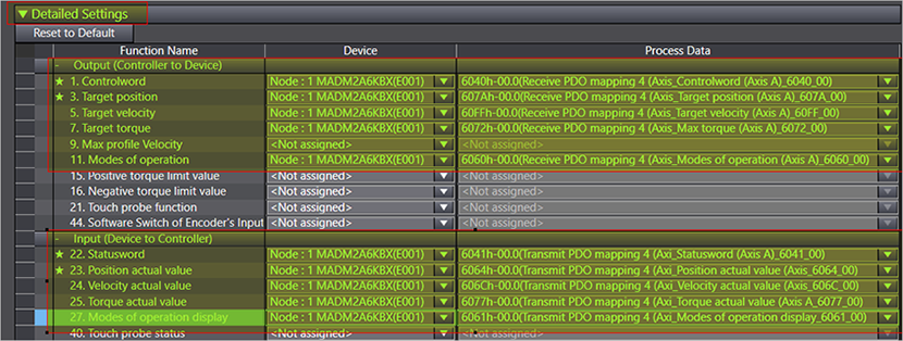
- Set the command pulse and travel distance per motor revolution.The motors of the MINAS A6 Multi series have an encoder resolution of 23 bits (8388608 pulses).
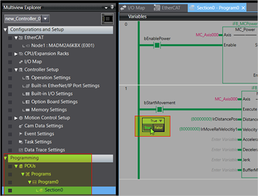
Program a simple positioning task
Download and run the project
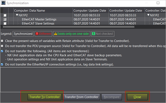
- Select the yellow triangle in the tool bar to go online, and then select Synchronize to synchronize the project.
- Select Transfer to Controller and Close when the transfer is completed.
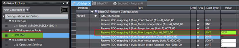
- Select I/O Map and set a maximum torque of 5000 (unit 0.1%) for axis A.
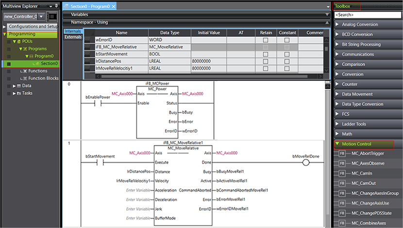
- Turn the variable bEnablePower to TRUE to enable servo control. Turn bStartMovement to TRUE to start the relative positioning of the axis.