Position control with TRIO host controller over EtherCAT
Before you start
Before operating this product, read the safety instructions in the following manuals:
This product is for industrial use only.
Electrical connections must be made by qualified electrical personnel.
Description
Step-by-step instructions will guide you through connecting a TRIO MC6N-ECAT host controller to a MINAS A6 Multi servo drive system. You will also learn how to program a simple positioning task in TRIO's Motion Perfect software. Communication is achieved using EtherCAT.
Available software
The following software is available free of charge in our Panasonic Download Center.
The following software can be downloaded from TRIO’s Web site (https://www.triomotion.com):
Motion Perfect software
Functional overview
A Panasonic MINAS A6 Multi servo drive system includes a power supply module, one or more 400V driver modules, and one or two motors connected to each driver module. Communication can be achieved through EtherCAT with any host controller that supports the CAN application protocol over EtherCAT (CoE).
Example
A servo drive system, consisting of a 15kW power supply module, an A-size 1.5kW two-axis driver module, and two servo motors with a rated power of 1.0kW and 1.5kW, is connected to a TRIO MC6N-ECAT host controller by an Ethernet cable to communicate via EtherCAT.
Use the following accessories:
1 x 400V AC power supply cable: Connects the MINAS A6 Multi power supply module to the main power supply (400V AC).
1 x 24V DC power supply cable: Connects the power supply unit (24V DC) and the host controller.
1 x grounding wire (M4 round terminal): Connects the PE terminals of the power supply module and the driver module.
2 x Panasonic motor cable: Connects the motor and the driver module.
2 x Panasonic encoder cable: Connects the encoder and the driver module.
1 x Ethernet cable: Connects the PC and the host controller.
1 x Ethernet cable (used for EtherCAT communication): Connects the host controller and the driver module.
1 x RJ11 communication cable (2 x RJ11 plug): Connects the power supply module and the driver module.
1 x feed bus bar (50mm) with end cap for the DC link bus (535V DC to 675V DC): Connects the power supply module and the driver module.
1 x feed bus bar (50mm) with end cap for the control bus (24V DC): Connects the power supply module and the driver module.

- (1) Power supply unit (24V DC)
- (2) TRIO MC6N-ECAT host controller
- (3) MINAS A6 Multi power supply module (400V AC, 15kW)
- (4) Two-axis MINAS A6 Multi driver module (1.5kW)
- (5) MINAS A6 servo motor B (1.5kW)
- (6) MINAS A6 servo motor A (1kW)
- (7) PC with Motion Perfect
Wiring
Recommendations for wiring
It is the customer's responsibility to apply the countermeasures that they consider necessary to comply with current regulations on wiring, safety and reducing EMI.
Do not forget to meet the specifications indicated in the hardware manual for each of the devices being wired. If any specifications in the manual conflict with the information in this document, the manufacturer's manual takes preference.
For detailed information on reducing EMI, please refer to Recommendations for EMC-compliant wiring of servo drivers and motors.
Bottom side connectors of the servo drive system
The image shows the most important connectors of a power supply module (left) and a driver module (right). Please refer to the technical documentation for details about other connectors.

- (1)
X102: Main power supply (400V AC)
Connect the 400V AC main power supply cable to X102. Connect the PE terminals of the power supply module and the driver module by a grounding wire.
- (2)
X11: Control power supply (24V DC)
Connect the 24V DC control power supply to X11.
- (3)
X105A: Motor A, (4) X105B: Motor B
Connect the motor cable for servo motor A to X105A and the motor cable for servo motor B to X105B.
- (4)
X9A: Encoder A, (6) X9B: Encoder B
Connect the cable of encoder A to X9A and the cable of encoder B to X9B.
Top side connectors of the servo drive system
The image shows the most important connectors of a power supply module (left) and a driver module (right). Please refer to the technical documentation for details about other connectors.

- (1)
X1: Internal communication connector on power supply module, (2) X1A: Internal communication connector on driver module
Connect X1 and X1A with the RJ11 communication cable.
- (3)
X6A: EtherCAT communication connector on driver module
Connect an Ethernet cable between the EtherCAT connector of the host controller and X6A of the driver module.
Front side connectors of the servo drive system
The image shows the most important connectors of a power supply module (left) and a driver module (right). Please refer to the technical documentation for details about other connectors.

- (1)
X7: USB connector (for driver configuration) on driver module
The driver module is configured using the PC configuration software PANATERM. Use a commercially available USB A to mini-B cable to connect the PC to the driver module.
- (2)
X104: DC link bus connectors on power supply module and driver module (535V DC to 675V DC), (3) X12: Control bus (24V DC) connectors on power supply module and driver module
Attach the bus bars to X104 and X12 to connect the DC circuits of the power supply module and the driver module.
- (4)
Connectors for DC circuits without and with bus bars
Connectors of the TRIO MC6N-ECAT host controller
The image shows the front view of the host controller.

- (1)
Programming port
Connect an Ethernet cable between this connector and the Ethernet port of your PC.
- (2)
EtherCAT port
Connect an Ethernet cable between this connector and the X6A connector of the MINAS A6 Multi driver module.
- (3)
24V power supply
Connect this connector to 24V DC.
Create a Motion Perfect project
Install Motion Perfect on your PC
The servo drive system is controlled with TRIO's Motion Perfect software. Install this software and the Panasonic ESI file on your PC.
- Download the Motion Perfect software from TRIO’s website and execute the installation file.
- Download the Panasonic ESI file (Panasonic_MINAS_A6Multi_V*.xml).
- Start Motion Perfect.
The download links can be found under Available software.
Create a new project in Motion Perfect
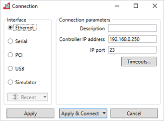
You must set the IP address for the Ethernet connection between your PC and the host controller. The default IP address of the host controller is 192.168.0.250. The IP address of your PC must be in the same IP range. In this example we use the IP address 192.168.0.10.
- Select the Motion Perfect icon on your desktop to start the software.
- On the Connection dialog, select Ethernet and enter the IP address of the host controller. Do not change the default value in IP port.
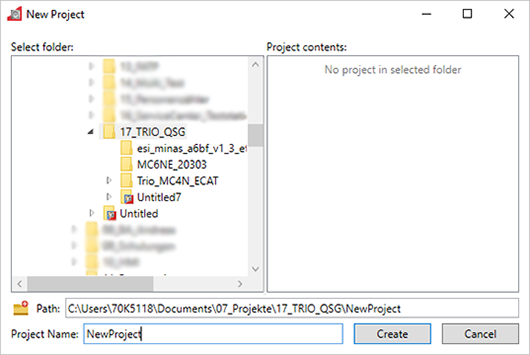
- Select New to create a new project.
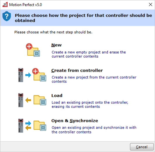
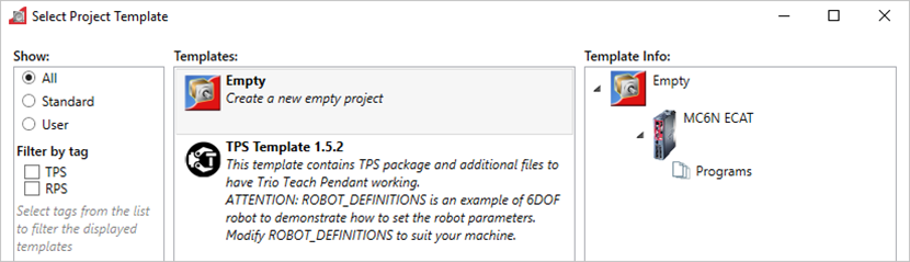
- Select Empty to create an empty project and click on Select. Then choose a folder and file name for your project.
If a warning appears that all controller content will be erased, make sure you have a backup of your projects on the PC.
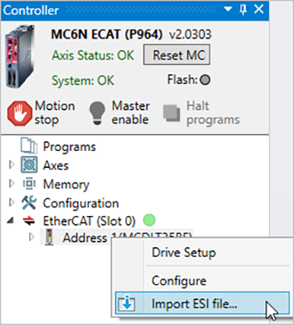
The axis status and the system status "OK" are now displayed in green color in the upper left corner of the screen. The EtherCAT slave is connected and ready.
- Go to EtherCAT (Slot 0), right-click Address 1, select Import ESI file, and browse to the ESI file on your PC.
Program a simple positioning task
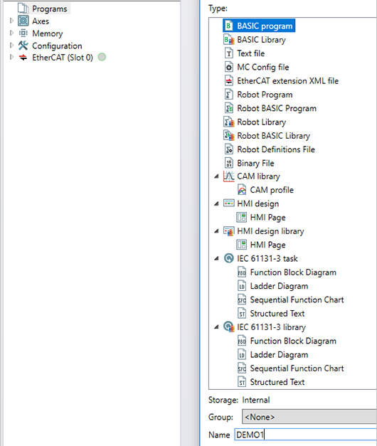
- Go to , enter a name for your program and select OK.
- To program the motion routine, perform the following steps.
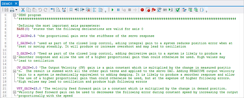
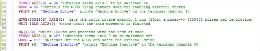
The code enables servo control, prints "Machine Active" in the Terminal window, turns the motor shaft by 1 revolution, waits 1 second (1000ms), and disables servo control again while displaying "Inactive" in the Terminal window.
Define the most important variables (gain values) using the BASE(0) instruction.
Define units, speeds, limits, etc.
Define inputs and other parameters.
Program the axis movement.
Most comments in these examples were copied from the Motion Perfect help file.
To copy the program code into your project, follow the link in the related topics.
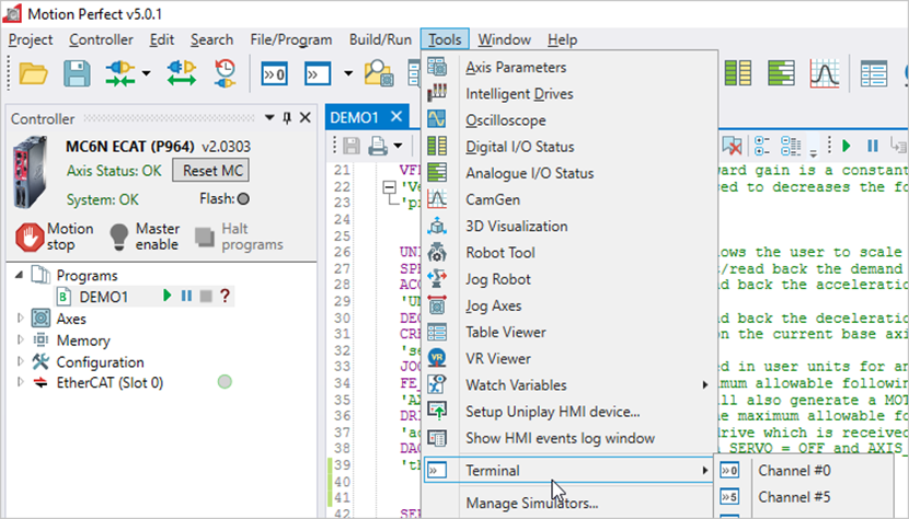
- To monitor the current status of the axis, open the Terminal window: Go to .
Demo program code
This is the program code of the application example in this section. To get started, copy the lines of the program code into your project.
'DEMO program
'###########################################################################
'Defining the most important axis parameters:
BASE(0) 'states that the following declarations are valid for axis 0
P_GAIN=2.5 'the proportional gain sets the stiffness of the servo response
I_GAIN=0.0 'used as part of the closed loop control, adding integral gain to a system reduces position error when at
'rest or moving steadily. It will produce or increase overshoot and may lead to oscillation
D_GAIN=0.0 'Used as part of the closed loop control, adding derivative gain to a system is likely to produce a
'smoother response and allow the use of a higher proportional gain than could otherwise be used. High values may
'lead to oscillation
OV_GAIN=0.0 'The Output Velocity (OV) gain is a gain constant which is multiplied by the change in measured positio
'n. The result is summed with all the other gain terms and applied to the servo DAC. Adding NEGATIVE output velocity
'gain to a system is mechanically equivalent to adding damping. It is likely to produce a smoother response and allow
'the use of a higher proportional gain than could otherwise be used, but at the expense of higher following errors.
'High values may lead to oscillation and produce high following errors
VFF_GAIN=23.0 'The velocity feed forward gain is a constant which is multiplied by the change in demand position.
'Velocity feed forward gain can be used to decreases the following error during constant speed by increasing the output
'proportionally with the speed
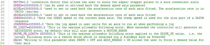
UNITS=1.0 'conversion factor that allows the user to scale the edges/ stepper pulses to a more convenient scale
SPEED=10000000.0 'can be used to set/read back the demand speed axis parameter
ACCEL=100000000.0 'used to set or read back the acceleration rate of each axis fitted. The acceleration rate is in
'UNITS /sec/sec
DECEL=100000000.0 'used to set or read back the deceleration rate of each axis fitted
CREEP=10000.0 'Sets the CREEP speed on the current base axis. The creep speed is used for the slow part of a DATUM
'sequence
JOGSPEED=1000000.0 'Sets the jog speed in user units for an axis to run at when performing a jog
FE_LIMIT=40000000.0 'This is the maximum allowable following error. When exceeded the controller will generate an
'AXISSTATUS error, by default this will also generate a MOTION_ERROR
DRIVE_FE_LIMIT= 2000000.0 'This is the maximum allowable following error applied to the DRIVE_FE value. i.e. the
'actual following error in a remote drive which is received via a fieldbus such as EtherCAT
DAC=0 'Writing to this parameter when SERVO = OFF and AXIS_ENABLE = ON allows the user to force a demand value for
'that axis
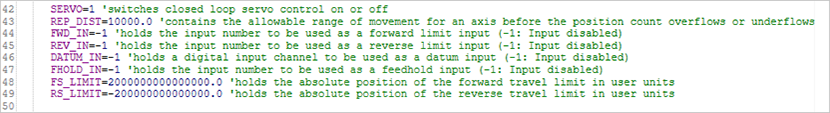
SERVO=1 'switches closed loop servo control on or off
REP_DIST=10000.0 'contains the allowable range of movement for an axis before the position count overflows or underflows
FWD_IN=-1 'holds the input number to be used as a forward limit input (-1: Input disabled)
REV_IN=-1 'holds the input number to be used as a reverse limit input (-1: Input disabled)
DATUM_IN=-1 'holds a digital input channel to be used as a datum input (-1: Input disabled)
FHOLD_IN=-1 'holds the input number to be used as a feedhold input (-1: Input disabled)
FS_LIMIT=2000000000000000.0 'holds the absolute position of the forward travel limit in user units
RS_LIMIT=-200000000000000.0 'holds the absolute position of the reverse travel limit in user units
SERVO AXIS(0) = ON 'addresses servo axis 0 to be switched on
WDOG = ON 'Controls the WDOG relay contact used for enabling external drives
PRINT #0, "Machine Active" 'prints "Machine Active" in the terminal channel #0
MOVE(83886080) AXIS(0) 'lets the motor rotate exactly 1 rpm (23bit encoder--> 8388608 pulses per revolution)
WAIT IDLE AXIS(0) 'waits until the axis movement is finished
WA(1000) 'waits 1000ms and proceeds with the rest of code
SERVO AXIS(0) = OFF 'addresses servo axis 0 to be switched off
WDOG = OFF 'switches Off the WDOG and hence the external drive
PRINT #0, "Machine Inactive" 'prints "Machine Inactive" in the terminal channel #0
Update the firmware
The firmware of the TRIO MC6N-ECAT controller can be updated with the Motion Perfect software. Download the firmware files from TRIO’s website. The download links can be found under Available software.
To update the firmware, go to and follow the instructions in the software.