Ladder Diagram and Function Block Diagram are programming languages that represent a program by means of standardized graphical symbols for programming elements.
Programming elements in LD include a power rail, contacts, coils, input and output variables, functions, function blocks, jumps and returns, horizontal and vertical lines.
FBD uses similar programming elements but does not have a power rail, contacts, and coils. In this section, examples and descriptions refer to LD unless stated otherwise.
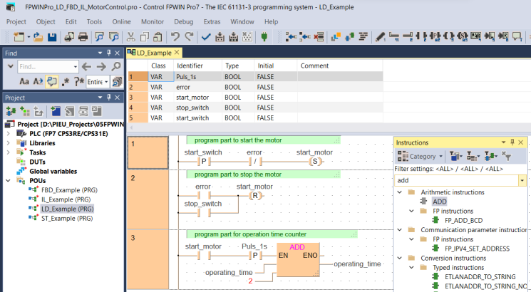
Example for LD
Three networks programmed in ladder diagram:

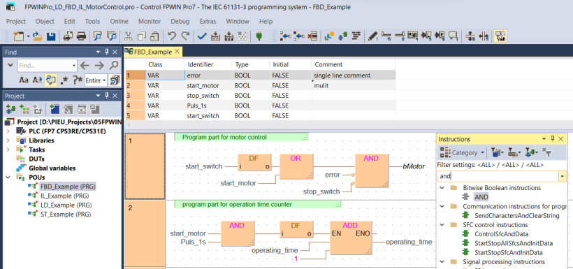
Example for FBD
Two networks programmed in function block diagram:

The program is displayed in the programming window with POU header and POU body. The POU body is divided into networks. Each network has a network header containing the network number and information, e.g. labels or breakpoints.
To open the online help for a function, function block, or operator, select the object in the POU body and press <F1>.