


 Unit_AnalogInput_FP0R_AD4
Function block to read from an FP0R-AD4 unit.
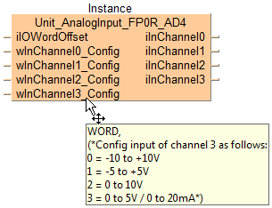
This function block reads converted digital values from the analog input channels of the analog unit. The converted digital values are stored per channel in the output variables iInChannel0 to iInChannel3.
The analog input ranges are also set with this function block.
The number of channels must be set with the DIP switches.
Input
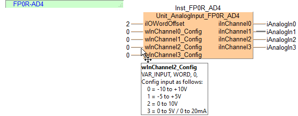
Set the offset of the first WX/WY address of the analog unit according to its installation position.
For analog expansion units connected directly to the CPU (without adapter): Use ExpansionUnitToIOWordOffset_FP0 or make the following settings: 2 (WX2/WY2) for unit number 1, 4 (WX4/WY4) for unit number 2, 6 (WX6/WY6) for unit number 3
For analog expansion units connected to the CPU via an adapter: Use ExpansionUnitToIOWordOffset_FPX_FP0 or select the offset from the table.
Unit position relative to the adapter |
Adapter position relative to the CPU |
|||||||
|---|---|---|---|---|---|---|---|---|
1st unit |
2nd unit |
3rd unit |
4th unit |
5th unit |
6th unit |
7th unit |
8th unit |
|
1st unit |
30 |
40 |
50 |
60 |
70 |
80 |
90 |
100 |
2nd unit |
32 |
42 |
52 |
62 |
72 |
82 |
92 |
102 |
3rd unit |
34 |
44 |
54 |
64 |
74 |
84 |
94 |
104 |
Set the voltage or current range for the analog input channel.
Output
DIP switches 1 and 2 must be ON to use 14-bit mode. DIP switches 3 and 4 are used to set the number of channels, and DIP switch 5 is used to turn averaging on or off.
The DIP switch settings will become effective when the power is turned from OFF to ON.
2 (0 and 1) |
4 (0 to 3) |
|
|---|---|---|
 |
 |
 |
No averaging: Conversion data is set for the specified input contact point area for each A/D conversion, on each channel.
Averaging: On each channel, for each A/D conversion, the maximum and minimum values from the data of the last ten times are excluded, the data from the other eight times is averaged and the result is set.
No averaging |
Averaging |
|
|---|---|---|
|
 |
 |
Voltage input |
Current input |
|---|---|
 Connect the input instrument between the V and the COM terminal. |
 Connect the V and the I terminals. Connect the input instrument between the bridge the and COM terminal. |
-10V to +10V DC input |
-5V to +5V DC input |
0V to 5V DC input |
|||
|---|---|---|---|---|---|
Digital value (INT) |
Analog value |
Digital value (INT) |
Analog value |
Digital value (INT) |
Analog value |
-8000 |
-10V |
-8000 |
-5V |
0 |
0.0V |
-4000 |
-5V |
-4000 |
-2.5V |
4000 |
1.25V |
0 |
0V |
0 |
0V |
8000 |
2.5V |
+4000 |
+5V |
+4000 |
+2.5V |
8000 |
3.75V |
+8000 |
+10V |
+8000 |
+5V |
16000 |
5.0V |
0V to 10V DC input |
0mA to 20mA input |
||
|---|---|---|---|
Digital value (INT) |
Analog value |
Digital value (INT) |
Analog value |
0 |
0.0V |
0 |
0.0mA |
4000 |
2.5V |
3200 |
4.0mA |
8000 |
5.0V |
6400 |
8.0mA |
12000 |
7.5V |
9600 |
12.0mA |
16000 |
10.0V |
12800 |
16.0mA |
16000 |
20.0mA |
||
This command description provides basic hardware documentation only. For detailed technical information, consult the manual:

All input and output variables used for programming this function have been declared in the POU header. The same POU header is used for all programming languages.
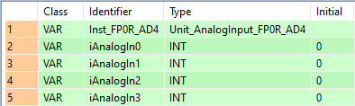
VAR
	Inst_FP0R_AD4: Unit_AnalogInput_FP0R_AD4;
	iAnalogIn0: INT:=0;
	iAnalogIn1: INT:=0;
	iAnalogIn2: INT:=0;
	iAnalogIn3: INT:=0;
END_VARUse ExpansionUnitNumberToIOWordOffset_FP0 or ExpansionUnitNumberToIOWordOffset_FPX_FP0 to calculate the word offset of the analog unit connected to the CPU.
BODY
    WORKSPACE
        NETWORK_LIST_TYPE := NWTYPELD ;
    END_WORKSPACE
    NET_WORK
        NETWORK_TYPE := NWTYPELD ;
        NETWORK_LABEL :=  ;
        NETWORK_TITLE :=  ;
        NETWORK_HEIGHT := 8 ;
        NETWORK_BODY
B(B_COMMENT,,FP0R-AD4,2,0,17,1,);
B(B_FB,Unit_AnalogInput_FP0R_AD4!,Inst_FP0R_AD4,19,1,34,8,,?BiIOWordOffset?BwInChannel0_Config?BwInChannel1_Config?BwInChannel2_Config?BwInChannel3_Config?CiInChannel0?CiInChannel1?CiInChannel2?CiInChannel3);
B(B_VARIN,,2,17,2,19,4,);
B(B_VAROUT,,iAnalogIn0,34,2,36,4,);
B(B_VARIN,,0,17,3,19,5,);
B(B_VAROUT,,iAnalogIn1,34,3,36,5,);
B(B_VARIN,,0,17,4,19,6,);
B(B_VAROUT,,iAnalogIn2,34,4,36,6,);
B(B_VARIN,,0,17,5,19,7,);
B(B_VAROUT,,iAnalogIn3,34,5,36,7,);
B(B_VARIN,,0,17,6,19,8,);
L(1,0,1,8);
        END_NETWORK_BODY
    END_NET_WORK
END_BODYInst_FP0R_AD4(iIOWordOffset := 2,
wInChannel0_Config := 0,
wInChannel1_Config := 0,
wInChannel2_Config := 0,
wInChannel3_Config := 0,
iInChannel0 => iAnalogIn0,
iInChannel1 => iAnalogIn1,
iInChannel2 => iAnalogIn2,
iInChannel3 => iAnalogIn3);