

 FP_DECODE
Decode hexadecimal -> bit state
This FP instruction decodes the contents of data specified by s1_Start according to the contents of s2_Control if the trigger EN is set to TRUE. The decoded result is stored in the area starting from d_Start.
FP_DECODE is the inverse instruction of FP_ENCODE.

Input
Source area or equivalent constant to be decoded
Control data to specify the starting bit position and number of bits to be decoded
Output
Starting address for storing decoded data (destination)
The variables s1_Start, s2_Control and d_Start have to be of the same data type.
Examples2_Control=16#404

The decoded data TRUE is stored in bit position 7 of d_Start.
All bits except bit 7 are filled with zeros.
The contents of the 2^nL bit segment from nH bit of the area specified by s1_Start are decoded (where nL is the number of bits to be decoded).
The decoded results are stored in the 2^nL bit segments starting from the area specified by d_Start (where nH is the conversion start bit). Invalid bits in the specified area for the result are filled with zeros.
Description of s2_Control
s2_Control specifies the starting bit position and the number of bits to be decoded using hexadecimal data.

The bits marked "-" are invalid. |
|||||
Set value 16#0–16#F |
(3) Starting bit position to be decoded |
Set value 16#0–16#8 |
(4) Number of decoded bits |
||
16#0 |
0 |
16#0 |
0 |
||
16#1 |
1 |
16#1 |
1 |
||
16#2 |
2 |
16#2 |
2 |
||
16#3 |
3 |
16#3 |
3 |
||
16#4 |
4 |
16#4 |
4 |
||
16#5 |
5 |
16#5 |
5 |
||
16#6 |
6 |
16#6 |
6 |
||
16#7 |
7 |
16#7 |
7 |
||
16#8 |
8 |
16#8 |
8 |
||
16#9 |
9 |
||||
16#A |
10 |
||||
16#B |
11 |
||||
16#C |
12 |
||||
16#D |
13 |
||||
16#E |
14 |
||||
16#F |
15 |
||||
Relationship between number of bits and occupied data area for decoded result
Number of bits to be decoded |
Data area required for the result |
Number of decoded bits (result) |
|---|---|---|
1 |
1 word |
2-bit 1) |
2 |
1 word |
4-bit 1) |
3 |
1 word |
8-bit 1) |
4 |
1 word |
16-bit |
5 |
2 words |
32-bit |
6 |
4 words |
64-bit |
7 |
8 words |
128-bit |
8 |
16 words |
256-bit |
1) Invalid bits in the data area required for the result are filled with zeros.
Example of decoded data
When decoding 4-bit data, 16-bit data for the decoded result is shown below.
Decoding condition: s2_Control
Starting bit position 0: 16#0
Number of bits to be decoded: 16#4 (4 bits)
Data to be decoded (4 bits) |
Decoded result |
|
|---|---|---|
Hex. |
Dec. |
|
16#0000 |
0 |
0000 0000 0000 0001 |
16#0001 |
1 |
0000 0000 0000 0010 |
16#0010 |
2 |
0000 0000 0000 0100 |
16#0011 |
3 |
0000 0000 0000 1000 |
16#0100 |
4 |
0000 0000 0001 0000 |
16#0101 |
5 |
0000 0000 0010 0000 |
16#0110 |
6 |
0000 0000 0100 0000 |
16#0111 |
7 |
0000 0000 1000 0000 |
16#1000 |
8 |
0000 0001 0000 0000 |
16#1001 |
9 |
0000 0010 0000 0000 |
16#1010 |
10 |
0000 0100 0000 0000 |
16#1011 |
11 |
0000 1000 0000 0000 |
16#1100 |
12 |
0001 0000 0000 0000 |
16#1101 |
13 |
0010 0000 0000 0000 |
16#1110 |
14 |
0100 0000 0000 0000 |
16#1111 |
15 |
1000 0000 0000 0000 |
if the area specified using the index modifier exceeds the limit.
if 1 £ nL £ 8, where nL is the number of bits to be encoded/decoded.
if 1 £ nH + nL £ 16, where nH is the conversion start bit and nL is the number of bits to be encoded/decoded.
if the memory area used by the decoded result exceeds the limit.

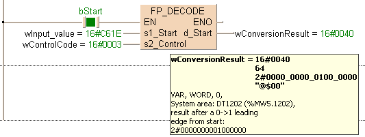
All input and output variables used for programming this function have been declared in the POU header. The same POU header is used for all programming languages.

	VAR
		bStart: BOOL:=FALSE;
			(*activates the function*)
		wInput_value: WORD:=2#1100011000011110;
		wControlCode: WORD:=16#0003;
			(*specifies decoding*)
		wConversionResult: WORD:=0;
			(*result after a 0->1 leading
edge from start:
2#0000000001000000*)
END_VARWhen the variable bStart is set to TRUE, the function is carried out.


BODY
    WORKSPACE
        NETWORK_LIST_TYPE := NWTYPELD ;
        ACTIVE_NETWORK := 0 ;
    END_WORKSPACE
    NET_WORK
        NETWORK_TYPE := NWTYPELD ;
        NETWORK_LABEL :=  ;
        NETWORK_TITLE :=  ;
        NETWORK_HEIGHT := 6 ;
        NETWORK_BODY
B(B_CONTACT,,bStart,8,1,10,3,);
B(B_VARIN,,wInput_value,11,2,13,4,);
B(B_VARIN,,wControlCode,11,3,13,5,);
B(B_VAROUT,,wConversionResult,21,2,23,4,);
B(B_F,FP_DECODE!,,13,0,21,5,,?DEN?Ds1_Start?Ds2_Control?AENO?Cd_Start);
L(10,2,13,2);
L(1,2,8,2);
L(1,0,1,6);
        END_NETWORK_BODY
    END_NET_WORK
END_BODY
IF start then
    FP_DECODE(s1_Start := wInput_value,
              s2_Control := wControlCode,
              d_Start => wConversionResult);
END_IF;