


 Unit_AnalogInput_FP0_TC4_TC8
Function block to read from an FP0-TC4 or FP0-TC8 unit.
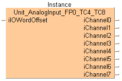
This function block reads converted digital values from the analog input channels of the analog unit. The converted digital values are stored per channel in the output variables iInChannel0 to iInChannel3 (FP0-TC4) or iChannel0 to iChannel7 (FP0-TC8).
The thermocouple type, the temperature unit (°C, °F), and the number of input channels must be set with the DIP switches.
Input
Set the offset of the first WX/WY address of the analog unit according to its installation position.
For analog expansion units connected directly to the CPU (without adapter): Use ExpansionUnitToIOWordOffset_FP0 or make the following settings: 2 (WX2/WY2) for unit number 1, 4 (WX4/WY4) for unit number 2, 6 (WX6/WY6) for unit number 3
For analog expansion units connected to the CPU via an adapter: Use ExpansionUnitToIOWordOffset_FPX_FP0 or select the offset from the table.
Unit position relative to the adapter |
Adapter position relative to the CPU |
|||||||
|---|---|---|---|---|---|---|---|---|
1st unit |
2nd unit |
3rd unit |
4th unit |
5th unit |
6th unit |
7th unit |
8th unit |
|
1st unit |
30 |
40 |
50 |
60 |
70 |
80 |
90 |
100 |
2nd unit |
32 |
42 |
52 |
62 |
72 |
82 |
92 |
102 |
3rd unit |
34 |
44 |
54 |
64 |
74 |
84 |
94 |
104 |
Output
Returns the converted digital data from the analog unit by channel.
Wire broken: 8000 or 16000
The DIP switch settings will become effective when the power is turned from OFF to ON.
K |
J |
T |
R |
|
|---|---|---|---|---|
 |
 |
 |
 |
 |
°C |
°F |
|
|---|---|---|
|
 |
 |
2 (0 and 1) |
4 (0 to 3) |
6 (0 to 5) |
8 (0 to 7) |
|
|---|---|---|---|---|
|
 |
 |
 |
 |

This command description provides basic hardware documentation only. For detailed technical information, consult the manual:

All input and output variables used for programming this function have been declared in the POU header. The same POU header is used for all programming languages.
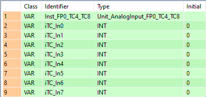
VAR
	Inst_FP0_TC4_TC8: Unit_AnalogInput_FP0_TC4_TC8;
	iTC_In0: INT:=0;
	iTC_In1: INT:=0;
	iTC_In2: INT:=0;
	iTC_In3: INT:=0;
	iTC_In4: INT:=0;
	iTC_In5: INT:=0;
	iTC_In6: INT:=0;
	iTC_In7: INT:=0;
END_VARUse ExpansionUnitNumberToIOWordOffset_FP0 or ExpansionUnitNumberToIOWordOffset_FPX_FP0 to calculate the word offset of the analog unit connected to the CPU.
BODY
    WORKSPACE
        NETWORK_LIST_TYPE := NWTYPELD ;
        ACTIVE_NETWORK := 0 ;
    END_WORKSPACE
    NET_WORK
        NETWORK_TYPE := NWTYPELD ;
        NETWORK_LABEL :=  ;
        NETWORK_TITLE :=  ;
        NETWORK_HEIGHT := 17 ;
        NETWORK_BODY
B(B_COMMENT,,Analog Unit TC4 TC8ø^Usage with FPX,2,0,22,2,);
B(B_COMMENT,,Function block of the Analog UnitFP0_A80 to read the Analog Input Dataø^Range K~J Type ( -100~1°C to 500~1°C--> -1001 to 5001 or -148~1°F to 790~1°F --> -1481 to 7901)ø^Range T Type: ( -100~1°C to 400~1°C --> -1001 to 4001 or  -148~1°F to 752~1°F --> -1481 to 7521)ø^Range R Type: (0°C to 1500~1°C --> 0 to 15001 or 32°F to 1590~1°F --> 320 to 15901)ø^8000(When the thermocouple is broken),28,1,73,6,);
B(B_VARIN,,1,1,8,3,10,);
B(B_VARIN,,2,1,9,3,11,);
B(B_FB,Unit_AnalogInput_FP0_TC4_TC8!,fbInstance10,28,7,43,17,,?BiIOWordOffset?AiChannel0?AiChannel1?AiChannel2?AiChannel3?AiChannel4?AiChannel5?AiChannel6?AiChannel7);
B(B_F,ExpansionUnitNumberToIOWordOffset_FPX_FP0!,,3,7,25,11,,?DiFPX_ExpansionUnitNumber?DiFP0_ExpansionUnitNumber?AiIOWordOffset);
L(25,9,28,9);
L(1,0,1,17);
        END_NETWORK_BODY
    END_NET_WORK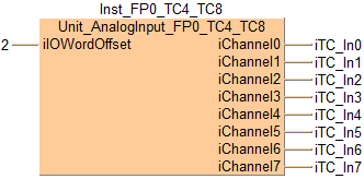
END_BODYInst_FP0_TC4_TC8(iIOWordOffset := 2,
iChannel0 => iTC_In0,
iChannel1 => iTC_In1,
iChannel2 => iTC_In2,
iChannel3 => iTC_In3,
iChannel4 => iTC_In4,
iChannel5 => iTC_In5,
iChannel6 => iTC_In6,
iChannel7 => iTC_In7);