


 SYS1 RS485 response time control
This changes the communication conditions based on the RS485 of the COM port or Tool port, in response to the contents specified by the character constant.
This instruction is valid only if the setting on the controller side has been set to the computer link mode or the PLC link mode. It is invalid in the general communication mode.
Executing this instruction does not change the settings in the system registers.
We recommend using differential execution with this instruction.
When the power supply to the PLC is off, the settings set by this instruction are cleared. (The set value will become 0.) If the mode is switched to the PROG mode after the instruction has been executed, however, the settings will be retained.
If a commercial RS232C/RS485 converter is being used in the PLC link mode, this instruction should be programmed in all of the stations (PLCs) connected to the link.
Separate first and second keywords with a comma "," and do not use spaces.
The port response time specified by the first keyword is delayed based on the contents specified by the second keyword. This instruction is used to delay the response time on the PLC side until the state is reached in which commands can be sent by an external device and responses can be received from the PLC.
The first and second keywords are separated by a comma.
When a commercial RS232C/RS485 converter is being used to carry out communication between a personal computer and the FP-å, this instruction is used to return the PLC response after switching of the enable signal has been completed on the converter side.

TOOL,WAITn
TOOL |
Port used TOOL: Tool port COM1: COM1 port COM2: COM2 port |
WAITn |
Response time WAIT0–WAIT999 (n: 0–999) |
If the communication mode has been set to the computer link mode, the set time is the scan time x n (n: 0 to 999).
If the communication mode has been set to the PLC link mode, the set time is nms (n: 0 to 999).
If n = 0, the delay time set by this instruction will be set to "None".
if any character other than a keyword is specified
if no comma is between the first and second keywords
if small letters of the alphabet are used to specify the keyword
if no communication cassette has been installed when COM1 or COM2 has been set
if any character other than a keyword is specified
if no comma is between the first and second keywords
if small letters of the alphabet are used to specify the keyword
if no communication cassette has been installed when COM1 or COM2 has been set

All input and output variables used for programming this function have been declared in the POU header. The same POU header is used for all programming languages.

	VAR
		bSetEdge: BOOL:=FALSE;
		DT_value: DT:=DT#2010-06-30-11:15:00;
		bEno: BOOL:=FALSE;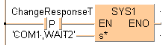
END_VARWhen ChangeResponseT turns on, the response time for COM port 1 is delayed by 2ms.
BODY
    WORKSPACE
        NETWORK_LIST_TYPE := NWTYPELD ;
        ACTIVE_NETWORK := 0 ;
    END_WORKSPACE
    NET_WORK
        NETWORK_TYPE := NWTYPELD ;
        NETWORK_LABEL :=  ;
        NETWORK_TITLE :=  ;
        NETWORK_HEIGHT := 5 ;
        NETWORK_BODY
B(B_F,E_SET_RTC_DT!,Instance,20,1,28,5,,?DEN?DIN?AENO);
B(B_VARIN,,DT_value,18,3,20,5,);
B(B_CONTACT,,bSetEdge,7,2,9,4,R);
B(B_COIL,,bEno,37,2,39,4,);
L(1,3,7,3);
L(9,3,20,3);
L(28,3,37,3);
L(1,0,1,5);
        END_NETWORK_BODY
    END_NET_WORK
END_BODYThe values entered at s* will be right aligned automatically by the compiler.