

 SYS2
SYS2Change system register settings for PC link area

You can change the values in system registers 40 - 47 (with the FP0R, FP-S 32k, FP-X also 50 - 57), PC link area.
While the PLC is in RUN mode, SYS2 changes the settings for the specified system registers. s_Start contains the new values for those system registers defined between d_Start and d_End.
Executing this instruction does not rewrite the contents of the system ROM in the control unit. As a result, turning the power supply off and then on again rewrites the contents of the system registers specified by the tool software.
A value between 40 and 47 should be specified for d_Start or d_End. Also, the values should always be specified in such a way that d_Start£d_End.
The values of the system registers change, so a verification error may occur when the program is verified.
Input
Contains new values for the system registers defined by remaining two variables.
First system register (between 40-47) to receive new value.
must be a constantLast system register (between 40-47) to receive new value.
must be a constantif d_Start > d_End
if the specified value is outside the ranges specified for the various system registers setting values
if d_Start > d_End
if the specified value is outside the ranges specified for the various system registers setting values
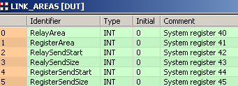
With a Data Unit Type (DUT) you can define a data unit type that is composed of other data types. A DUT is first defined in the DUT pool and then processed like the standard data types (BOOL, INT, etc.) in the list of global variables or the POU header.


All input and output variables used for programming this function have been declared in the POU header. The same POU header is used for all programming languages.

	VAR
		LinkAreas: @'LINK_AREAS':=RelayArea := 64, RegisterArea := 128;
		SetLinkAreas: BOOL:=FALSE;
END_VARChanges the values for the PC link area system registers 40 through 45 as defined in LinkAreas when SetLinkAreas turns on.


BODY
    WORKSPACE
        NETWORK_LIST_TYPE := NWTYPELD ;
        ACTIVE_NETWORK := 0 ;
    END_WORKSPACE
    NET_WORK
        NETWORK_TYPE := NWTYPELD ;
        NETWORK_LABEL :=  ;
        NETWORK_TITLE :=  ;
        NETWORK_HEIGHT := 6 ;
        NETWORK_BODY
B(B_F,SYS2!,Instance,10,0,16,6,,?DEN?Ds_Start?Hd_Start?Hd_End?AENO);
B(B_VARIN,,SetLinkAreas,8,1,10,3,);
B(B_VARIN,,LinkAreas.RelayArea,8,2,10,4,);
B(B_VARIN,,40,8,3,10,5,);
B(B_VARIN,,45,8,4,10,6,);
L(1,0,1,6);
        END_NETWORK_BODY
    END_NET_WORK
END_BODY