


 F173_PulseOutput_PWM_Hz
Pulse output instruction with channel specification (PWM output)
This instruction delivers a pulse width modulated output signal according to the specified DUT. Pulses are output from the specified channel when the control flag for this channel is FALSE and the execution condition is TRUE.
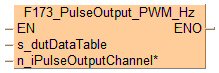
Input
Starting address of area containing the data table
Pulse output channel:
FP-XH C30 T/P: 0–3
FP-XH C60 T/P: 0–5
FPS: 0,2
FP-X, FP-XH Relay: 0,1
FP-X, FP-XH 16k Transistor: 0–2
FP0R, FP0H, FP-X, FP-XH 32 Transistor: 0–3
FP-XH 32k Transistor: 0–5
Use the following predefined DUT: F173_PulseOutput_PWM_Hz_DUT
The following parameters can be specified in the DUT:
Approximate frequency
Duty ratio (for pulse duration and period)
The ratio between the pulse duration and the period of a rectangular waveform. For a pulse train in which the pulse duration is 1ms and the pulse period is 4ms, the duty ratio is 0.25 or 25%.
The duty ratio, particularly when it is close to the minimum or maximum value, may differ from the specified duty ratio, depending on the load voltage and the load current.
The duty ratio can be changed for each scan.
The frequency constant K cannot be changed during execution of the instruction. If it is changed, it will have no effect on the frequency but on the resolution of the duty ratio.
If the duty ratio is changed to a value outside the permissible range while the instruction is being executed, the duty ratio is adjusted to the maximum value. When execution of the instruction begins, an operation error is displayed.
If the frequency is changed to a value outside the permissible range while the instruction is being executed, the resolution is adjusted to 100. When execution of the instruction begins, no operation error is displayed.
If the duty is changed to 100% or higher while the instruction is being executed, the frequency is adjusted to the maximum value at the specified resolution. When execution of the instruction begins, no operation error is displayed.
If both the main program and the interrupt program contain code for the same channel, make sure both are not executed simultaneously.
FP0H, FP0R, FP-XH, FP-X: When a pulse output instruction is executed and pulses are being output, the pulse output control flag (e.g. sys_bIsPulseChannel0Active) of the corresponding channel is TRUE. No other pulse output instruction can be executed as long as this flag is TRUE.
FP0H, FP0R, FP-XH, FP-X: Set “PWM output” for the desired channel in the system registers.

All input and output variables used for programming this function have been declared in the POU header. The same POU header is used for all programming languages.
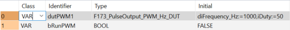
	VAR
		dutPWM1: F173_PulseOutput_PWM_Hz_DUT:=diFrequency_Hz:=1000,iDuty:=50;
		bRunPWM: BOOL:=FALSE;
	END_VAR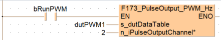
BODY
    WORKSPACE
        NETWORK_LIST_TYPE := NWTYPELD ;
    END_WORKSPACE
    NET_WORK
        NETWORK_TYPE := NWTYPELD ;
        NETWORK_LABEL :=  ;
        NETWORK_TITLE :=  ;
        NETWORK_HEIGHT := 5 ;
        NETWORK_BODY
B(B_CONTACT,,bRunPWM,6,1,8,3,);
B(B_F,F173_PulseOutput_PWM_Hz!,,15,0,28,5,,?DEN?Ds_dutDataTable?Hn_iPulseOutputChannel?AENO);
B(B_VARIN,,dutPWM1,13,2,15,4,);
B(B_VARIN,,2,13,3,15,5,);
L(1,0,1,5);
L(1,2,6,2);
L(8,2,15,2);
        END_NETWORK_BODY
    END_NET_WORK
END_BODYIf (bRunPWM) Then
F173_PulseOutput_PWM_Hz(s_dutDataTable := dutPWM1, n_iPulseOutputChannel := 2);
END_IF;