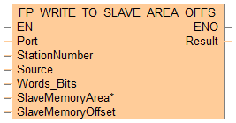


 FP_WRITE_TO_SLAVE_AREA_OFFS
Write data to slave with offset
Use this instruction to write data from a master to a slave via the communication port using the MEWTOCOL-COM or Modbus RTU protocol, as defined in the system registers of the port used. Make sure the same protocol is set for master and slave. Master and slave must have matching memory areas.
For data transmissions using the Modbus protocol, the compiler generates Modbus commands based on the Modbus reference numbers.
Input
Specifies the communication ports depending on the PLC type:
COM port e.g. SYS_COM0_PORT
Ethernet port e.g. SYS_ETHERNET_USER_CONNECTION_1
MCU/SCU e.g. 16#xx01 (xx = slot number) in COM01
Station number of the slave (MEWTOCOL: 1–99,MODBUS: 1–247)
Set to 1, if a SYS_ETHERNET_USER_CONNECTION_xx is applied to input Port
Word area or register on the master unit for the data to be written to the slave.
Number of words (bits) to be transmitted.
Either:
Number of words
for Modbus RTU: 16#001–16#07F
for MEWTOCOL-COM: 16#001–16#1FD or 16#001–16#1B (FP0, FP-e)
Or:
Control word for bit transfer: 16#8T0F with T for a bit transfer to the master and F for a bit transfer to the slave (does not apply to FP7).
Memory area on the slave where to store the data (destination = SlaveMemoryArea + SlaveMemoryOffset).
Memory area type |
System variable |
|---|---|
Internal flags |
|
Link flags |
|
External inputs |
|
External outputs |
|
Internal flags |
|
Timer/counter set value |
|
Timer/counter elapsed value |
|
Data registers |
|
Link flags |
|
Link registers |
|
File registers |
|
Input registers |
|
Output registers |
Offset of the memory area where to store the data in the slave (destination = SlaveMemoryArea + SlaveMemoryOffset).
Output
For FP7 only: For a description of all error codes, please refer to the table of Modbus/MEWTOCOL communication error codes.
For other PLCs: set to 0

While sending: Master communication sending flag is TRUE
Sending done: Master communication sending flag is FALSE
Normal completion: FALSE
Abnormal completion: TRUE
if the area specified using the index modifier exceeds the limit.
if the number of sent data specified by Words_Bits is incorrect.
if the area specified using the index modifier exceeds the limit.
if the number of sent data specified by Words_Bits is incorrect.

All input and output variables used for programming this function have been declared in the POU header. The same POU header is used for all programming languages.

	VAR
		bSetParameters: BOOL:=FALSE;
		wWriteToSlaveResult: WORD:=0;
			(*result of write to slave instruction*)
		iSlaveStationNumber: INT:=0;
			(*slave station number*)
		arrParameters: ARRAY [0..15] OF DINT;
			(*Array of parameters to be send to slave station*)
		iSlaveMemoryOffset: INT:=100;
		bBool: BOOL:=FALSE;
	END_VAR
	VAR CONSTANT
		iSlaveMemoryArea_Bool: INT:=10000;
			(*memory Area in slave station*)
		iSlaveMemoryArea_Word: INT:=5;
			(*memory Area in slave station*)
	END_VAR
	VAR
	END_VAR

BODY
    WORKSPACE
        NETWORK_LIST_TYPE := NWTYPELD ;
        ACTIVE_NETWORK := 0 ;
    END_WORKSPACE
    NET_WORK
        NETWORK_TYPE := NWTYPELD ;
        NETWORK_LABEL :=  ;
        NETWORK_TITLE :=  ;
        NETWORK_HEIGHT := 9 ;
        NETWORK_BODY
B(B_VARIN,,SYS_COM1_PORT,18,2,20,4,);
B(B_VARIN,,iSlaveStationNumber,18,3,20,5,);
B(B_VARIN,,arrParameters,11,4,13,6,);
B(B_CONTACT,,bSetParameters,4,1,6,3,);
B(B_VAROUT,,wWriteToSlaveResult,36,2,38,4,);
B(B_F,Size_Of_Var!,,13,5,20,7,,?D?C);
B(B_F,FP_WRITE_TO_SLAVE_AREA_OFFS!,,20,0,36,9,,?DEN?DnPort?DStationNumber?DSource?DWords_Bits?HSlaveMemoryArea?DSlaveMemoryOffset?AENO?CResult);
B(B_VARIN,,SYS_MEMORY_AREA_DT,18,6,20,8,);
B(B_VARIN,,iSlaveMemoryOffset,18,7,20,9,);
L(13,5,13,6);
L(1,2,4,2);
L(13,5,20,5);
L(6,2,20,2);
L(1,0,1,9);
        END_NETWORK_BODY
    END_NET_WORK
END_BODY
if (bSetParameters) then
    FP_WRITE_TO_SLAVE_AREA_OFFS(Port := SYS_COM1_PORT,
                                StationNumber := iSlaveStationNumber,
                                Source := arrParameters[0],
                                Words_Bits := Size_Of_Var(arrParameters[0]),
                                SlaveMemoryArea := SYS_MEMORY_AREA_DT,
                                SlaveMemoryOffset := iSlaveMemoryOffset,
                                Result => wWriteToSlaveResult);
end_if;