


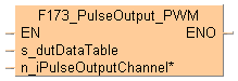
 F173_PulseOutput_PWM
Pulse output instruction with channel specification (PWM output)
This instruction delivers a pulse width modulated output signal according to the specified DUT. Pulses are output from the specified channel when the control flag for this channel is FALSE and the execution condition is TRUE.
Input
Starting address of area containing the data table
Pulse output channel:
FP-XH C30 T/P: 0–3
FP-XH C60 T/P: 0–5
FPS: 0,2
FP-X, FP-XH Relay: 0,1
FP-X, FP-XH 16k Transistor: 0–2
FP0R, FP0H, FP-X, FP-XH 32 Transistor: 0–3
FP-XH 32k Transistor: 0–5
Use the following predefined DUT: F173_PulseOutput_PWM_DUT
The following parameters can be specified in the DUT:
Approximate frequency
Duty ratio (for pulse duration and period)
The ratio between the pulse duration and the period of a rectangular waveform. For a pulse train in which the pulse duration is 1ms and the pulse period is 4ms, the duty ratio is 0.25 or 25%.
The duty ratio, particularly when it is close to the minimum or maximum value, may differ from the specified duty ratio, depending on the load voltage and the load current.
The duty ratio can be changed for each scan.
The frequency constant K cannot be changed during execution of the instruction. If it is changed, it will have no effect on the frequency but on the resolution of the duty ratio.
If the duty ratio is changed to a value outside the permissible range while the instruction is being executed, the duty ratio is adjusted to the maximum value. When execution of the instruction begins, an operation error is displayed.
If the frequency is changed to a value outside the permissible range while the instruction is being executed, the resolution is adjusted to 100. When execution of the instruction begins, no operation error is displayed.
If the duty is changed to 100% or higher while the instruction is being executed, the frequency is adjusted to the maximum value at the specified resolution. When execution of the instruction begins, no operation error is displayed.
If both the main program and the interrupt program contain code for the same channel, make sure both are not executed simultaneously.
FP-X, FP0R: When a pulse output instruction is executed and pulses are being output, the pulse output control flag (e.g. sys_bIsPulseChannel0Active) of the corresponding channel is TRUE. No other pulse output instruction can be executed as long as this flag is TRUE.
FPS: The high-speed counter control flag (e.g. sys_bIsHscChannel0ControlActive) and the pulse output control flag (e.g. sys_bIsPulseChannel0Active) are assigned to the same special internal flag number (e.g. R903A). Therefore, when a high-speed counter instruction or a pulse output instruction is executed, both the high-speed counter control flag (e.g. sys_bIsHscChannel0ControlActive) and the pulse output control flag (e.g. sys_bIsPulseChannel0Active) for the channel used are TRUE. No other high-speed counter instruction or pulse output instruction can be executed as long as this flag is TRUE.
FPS: Executing the circular interpolation control instruction F176_PulseOutput_Center sets the circular interpolation control flag (sys_bIsCircularInterpolationActive) to TRUE. The status of this flag is maintained until the target value is reached (even if the execution condition is no longer TRUE). During this time, other pulse output instructions cannot be executed.
FPS: Set any high-speed counter allocated to a pulse output channel to "Unused" in the system registers.
FP-X, FP0R: Set "PWM output" for the desired channel in the system registers.
We strongly recommend that you incorporate a forced stop option in your positioning program.
The status of the high-speed counter control flag or pulse output control flag may change while a scan is being carried out. For example, if the number of received bytes is read more than once different statuses may exist within one scan.
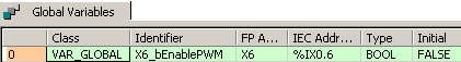
In the global variable list you define variables that can be accessed by all POUs in the project.
The DUT F173_PulseOutput_PWM_DUT is predefined in the FP Library.

All input and output variables used for programming this function have been declared in the POU header. The same POU header is used for all programming languages.

	VAR_EXTERNAL
		X6_bEnablePWM: BOOL:=FALSE;
	END_VAR
	VAR
		dutPWMControl: F173_PulseOutput_PWM_DUT:=iFrequencyValue := 1;
			(*iFrequencyValue := 1: f=2.0 Hz, T=502.5 ms;
*)
		iPulseWidthModulationDuty: INT:=500;
			(*500 = 50% duty*)
		@'': @'';
	END_VAR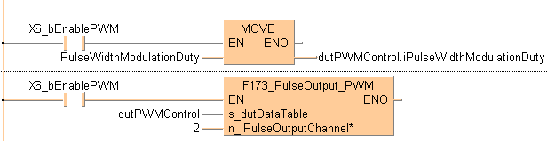
BODY
    WORKSPACE
        NETWORK_LIST_TYPE := NWTYPELD ;
        ACTIVE_NETWORK := 0 ;
    END_WORKSPACE
    NET_WORK
        NETWORK_TYPE := NWTYPELD ;
        NETWORK_LABEL :=  ;
        NETWORK_TITLE :=  ;
        NETWORK_HEIGHT := 5 ;
        NETWORK_BODY
B(B_CONTACT,,X6_bEnablePWM,5,2,7,4,);
B(B_F,E_MOVE!,Instance,16,1,22,5,,?DEN?D?AENO?C);
B(B_VARIN,,iPulseWidthModulationDuty,14,3,16,5,);
B(B_VAROUT,,dutPWMControl.iPulseWidthModulationDuty,22,3,24,5,);
L(7,3,16,3);
L(1,3,5,3);
L(1,0,1,5);
        END_NETWORK_BODY
    END_NET_WORK
    NET_WORK
        NETWORK_TYPE := NWTYPELD ;
        NETWORK_LABEL :=  ;
        NETWORK_TITLE :=  ;
        NETWORK_HEIGHT := 5 ;
        NETWORK_BODY
B(B_F,F173_PulseOutput_PWM!,Instance,16,0,29,5,,?DEN?Ds_dutDataTable?Hn_iPulseOutputChannel?AENO);
B(B_VARIN,,dutPWMControl,14,2,16,4,);
B(B_VARIN,,2,14,3,16,5,);
B(B_CONTACT,,X6_bEnablePWM,5,1,7,3,);
L(7,2,16,2);
L(1,2,5,2);
L(1,0,1,5);
        END_NETWORK_BODY
    END_NET_WORK
END_BODYIF (X6_bEnablePWM) then
dutPWMControl.iPulseWidthModulationDuty:=iPulseWidthModulationDuty;
END_IF;
IF (X6_bEnablePWM) then
F173_PulseOutput_PWM(s_dutDataTable := dutPWMControl,
n_iPulseOutputChannel := 2);
END_IF;