


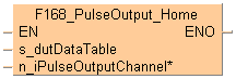
 F168_PulseOutput_Home
Home return
This instruction performs a home return according to the parameters in the specified DUT.Pulses are output from the specified channel when the control flag for this channel is FALSE and the execution condition is TRUE.
Input
Starting address of area containing the data table
Pulse output: 0 or 1
After a drive system has been switched on, there is a difference between the internal position value (elapsed value) and the mechanical position of the axis; this difference cannot be predetermined. The internal value must be synchronized with the actual position value of the axis. This is done by means of a home return, during which a position value is registered at a known reference point (home). During execution of a home return instruction, pulses are continuously output until the home input is enabled. The I/O allocation is determined by the channel used. To decelerate movement when near the home position, designate a near home input and set bit 4 of the special data register storing the pulse output control code (sys_wHscOrPulseControlCode) to TRUE and back to FALSE again. The value in the elapsed value area during a home return differs from the current value. When the return is completed, the elapsed value changes to 0.
Select one of two different operation modes:
Type 1: The home input is effective regardless of whether or not there is a near home input, whether deceleration is taking place, or whether deceleration has been completed.
Without near home input:

With near home input:

Type 2: The home input is effective only after deceleration (started by near home input) has been completed.

The following parameters can be specified in the DUT: F168_PulseOutput_Home_DUT
Control code
Initial and final speed
Target speed
Acceleration/deceleration time
Pulse stop (fixed)
The pulse output frequency changes according to the specified acceleration/deceleration time.
The difference between target and initial speed determines the slope of the ramps.
Set any high-speed counter allocated to a pulse output channel to "Unused" in the system registers.
When programs are being edited in RUN mode, pulse output stops but resumes after the program changes have been downloaded.
The high-speed counter control flag (e.g. sys_bIsHscChannel0ControlActive) and the pulse output control flag (e.g. sys_bIsPulseChannel0Active) are assigned to the same special internal flag number (e.g. R903A). Therefore, when a high-speed counter instruction or a pulse output instruction is executed, both the high-speed counter control flag (e.g. sys_bIsHscChannel0ControlActive) and the pulse output control flag (e.g. sys_bIsPulseChannel0Active) for the channel used are TRUE. No other high-speed counter instruction or pulse output instruction can be executed as long as this flag is TRUE.
Even when home input has occurred, executing this instruction causes pulse output to begin.
If the near home input is enabled while acceleration is in progress, deceleration will start.
If both the main program and the interrupt program contain code for the same channel, make sure both are not executed simultaneously.
We strongly recommend that you incorporate a forced stop option in your positioning program.
The status of the high-speed counter control flag or pulse output control flag may change while a scan is being carried out. For example, if the number of received bytes is read more than once different statuses may exist within one scan.
To run the FP0R in FP0 compatibility mode, you can download an FP0 program to the FP0R. Please note the following restrictions:
The FP0R supports signed 32-bit data for elapsed value and target value; the FP0 supports signed 24-bit data. In FP0 compatibility mode, counting and pulse output continue even if data exceeds the FP0 range.
The duty ratio is always 25% regardless of the settings in the instructions. With the pulse output method "pulse/direction", pulses are output approx. 300ms after the direction signal has been output; the motor driver characteristics are simultaneously taken into consideration.
The FP0R does not support the "no counting" setting. Instead, incremental counting is performed with the FP0 pulse output instructions set to "no counting".
The maximum pulse output frequency is 10000Hz.
Make sure the pulse output instruction does not use an output that is also being used as a normal output.
An FP0 program can only run in FP0 compatibility mode, if the PLC types (C10, C14, C16, C32, and T32) match exactly. FP0 compatibility mode is not available for the F32 type FP0R.
Channel and pulse output numbers
| Channel no. | Pulse output | Pulse output method |
0 |
Y0 |
Pulse |
Y2 |
Direction | |
1 |
Y1 |
Pulse |
Y3 |
Direction |
System variables for memory areas used. Values in parentheses are valid for FP0 T32.
Description |
System variable |
|
|---|---|---|
Pulse output: control flag for channel |
0 |
sys_bIsPulseChannel0Active |
1 |
sys_bIsPulseChannel1Active |
|
Pulse output: elapsed value for channel |
0 |
sys_diPulseChannel0ElapsedValue |
1 |
sys_diPulseChannel1ElapsedValue |
|
Pulse output: target value for channel |
0 |
sys_diPulseChannel0TargetValue |
1 |
sys_diPulseChannel1TargetValue |
|
High-speed counter or pulse output controlcode |
sys_wHscOrPulseControlCode |
|
| Channel no. | Home input |
0 |
X0 |
1 |
X1 |

All input and output variables used for programming this function have been declared in the POU header. The same POU header is used for all programming languages.
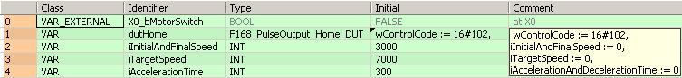
VAR_EXTERNAL
		X0_bMotorSwitch: BOOL:=FALSE;
			(*at X0*)
	END_VAR
	VAR
		dutHome: F168_PulseOutput_Home_DUT:=wControlCode := 16#102,
iInitialAndFinalSpeed := 0,
iTargetSpeed := 0,
iAccelerationAndDecelerationTime := 0;
		iInitialAndFinalSpeed: INT:=3000;
		iTargetSpeed: INT:=7000;
		iAccelerationTime: INT:=300;
		@'': @'';
	END_VAR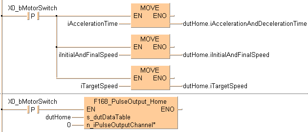
	BODY
    WORKSPACE
        NETWORK_LIST_TYPE := NWTYPELD ;
        ACTIVE_NETWORK := 0 ;
    END_WORKSPACE
    NET_WORK
        NETWORK_TYPE := NWTYPELD ;
        NETWORK_LABEL :=  ;
        NETWORK_TITLE :=  ;
        NETWORK_HEIGHT := 13 ;
        NETWORK_BODY
B(B_CONTACT,,X0_bMotorSwitch,4,2,6,4,R);
B(B_F,E_MOVE!,Instance,17,1,23,5,,?DEN?D?AENO?C);
B(B_VAROUT,,dutHome.iAccelerationAndDecelerationTime,23,3,25,5,);
B(B_F,E_MOVE!,Instance,17,5,23,9,,?DEN?D?AENO?C);
B(B_VAROUT,,dutHome.iInitialAndFinalSpeed,23,7,25,9,);
B(B_F,E_MOVE!,Instance,17,9,23,13,,?DEN?D?AENO?C);
B(B_VAROUT,,dutHome.iTargetSpeed,23,11,25,13,);
B(B_VARIN,,iAccelerationTime,15,3,17,5,);
B(B_VARIN,,iInitialAndFinalSpeed,15,7,17,9,);
B(B_VARIN,,iTargetSpeed,15,11,17,13,);
L(1,3,4,3);
L(6,3,17,3);
L(8,3,8,11);
L(8,11,17,11);
L(8,7,17,7);
L(1,0,1,13);
        END_NETWORK_BODY
    END_NET_WORK
    NET_WORK
        NETWORK_TYPE := NWTYPELD ;
        NETWORK_LABEL :=  ;
        NETWORK_TITLE :=  ;
        NETWORK_HEIGHT := 5 ;
        NETWORK_BODY
B(B_CONTACT,,X0_bMotorSwitch,4,1,6,3,R);
B(B_F,F168_PulseOutput_Home!,Instance,11,0,24,5,,?DEN?Ds_dutDataTable?Hn_iPulseOutputChannel?AENO);
B(B_VARIN,,dutHome,9,2,11,4,);
B(B_VARIN,,0,9,3,11,5,);
L(1,2,4,2);
L(6,2,11,2);
L(1,0,1,5);
        END_NETWORK_BODY
    END_NET_WORK
END_BODYIF DF(X0_bMotorSwitch) then
dutHome.iInitialAndFinalSpeed:=iInitialAndFinalSpeed
dutHome.iTargetSpeed:=iTargetSpeed
dutHome.iAccelerationAndDecelerationTime:=iAccelerationTime
END_IF;
IF DF(X0_bMotorSwitch) then
F168_PulseOutput_Home(s_dutDataTable := dutHome,
n_iPulseOutputChannel :=0);
END_IF;