

 F165_HighSpeedCounter_Cam
Cam control for FP0H
This instruction performs cam control as specified by the parameters in the specified DUT with a maximum of 32 target values according to the elapsed value of the high-speed counter. For every single cam output, the target value is set as a pair with an ON and an OFF set value.
An interrupt program can be executed whenever the elapsed value matches one of the target values.

Input
High-speed counter channel: 0–3
Starting address of area containing the data table
Output
Starting address (WR, WL or WY) of area containing the output word address, e.g. BOOL32_OVERLAPPING_DUT. Select the size (16 or 32 bits) according to the number set with diNumberOfTargetValuesAndOutputRelays.
Input
Create your own DUT using the following DUT as a sample: F165_HighSpeedCounter_Cam_8_Values_OnOff_DUT
The following parameters can be specified in the DUT:
Control code
Word address for outputs
Number of target values
(ON/OFF set values from F165_HighSpeedCounter_Target_Values_OnOff_DUT)
Maximum target value
Setting range: 1–2147483646 (16#1–16#7FFFFFFE)
Output
If the number of target values is in the range of 1–16, one word is used. If the number of target values is in the range of 17–32, two words are used.
Example: When the output address is set to "Internal flag", the starting word number of output address is set to "0", and the number of target values is set to "32", R0 to R1F are allocated as the address for the cam output.

When you have specified the output flag (Y), values are output both to the CPU output and to the operation memories.
Example

1000–4999 R100: ON
7000–8999 R101: ON
With F165_HighSpeedCounter_Cam, it is possible to perform the control with a specified maximum target. The settings for enabling/disabling the maximum target value control and the maximum target value are specified in the data table.
The data table varies in the range of 12 to 138 words depending on the number of target values and the specified maximum target value setting.
The maximum target value of the data table end is valid only when the target value control is set to 16#0010 (with maximum value) in dwCamControlCode. This setting can be omitted when the target value control is set to 16#0000 (without maximum value).
Enabled |
Disabled |
||
|---|---|---|---|
Counting range |
0 to target value |
Negative minimum value to positive maximum value |
|
Operation when the counting range is exceeded |
Incremental counting: |
When the elapsed value exceeds the target value, it is set to 0. |
When the elapsed value exceeds the positive maximum value, it returns to the negative minimum value. |
Decremental counting: The pointer of the data table moves from the last target value to target value 1. |
When the elapsed value falls below 0, it is set to the target value. |
When the elapsed value falls below the negative minimum value, it returns to the positive maximum value. |
|
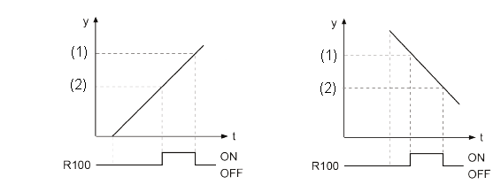
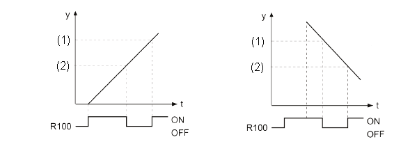
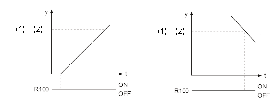
The output varies depending on the ON set value and OFF set value.
OFF set value > ON set value
When the elapsed value is larger than or equal to the ON set value and smaller than the OFF set value, the corresponding output bit turns on. When the elapsed value is out of range, the corresponding bit turns off.
Incremental counting: |
Decremental counting: |
|---|---|
OFF set value (1) > ON set value (2)  |
|
ON set value > OFF set value
When the elapsed value is smaller than the ON set value and larger than or equal to the OFF set value, the corresponding output bit turns off. When the elapsed value is out of range, the corresponding bit turns on.
Incremental counting: |
Decremental counting: |
|---|---|
ON set value (1) > OFF set value (2)  |
|
ON set value = OFF set value
When the elapsed value is out of range, the corresponding bit turns off.
Incremental counting: |
Decremental counting: |
|---|---|
ON set value (1) = OFF set value (2)  |
|
Select the high-speed counter input for the desired channel in the system registers.
When a high-speed counter instruction is executed, the high-speed counter control flag (e.g. sys_bIsHscChannel0ControlActive) for the channel used turns to TRUE. No other high-speed counter instruction using the same channel can be executed as long as the control flag is TRUE.
This instruction can be executed simultaneously on a maximum of two channels.
To cancel execution of an instruction, set bit 3 of the data register storing the high-speed counter control code (sys_wHscOrPulseControlCode) to TRUE. The high-speed counter control flag then changes to FALSE. To re-enable execution of the high-speed counter instruction, reset bit 3 to FALSE. When you set bit 3 of sys_wHscOrPulseControlCode to TRUE, this also disables the maximum target value control. When the maximum target value control is stopped, the cam output is held and the high-speed counter continues counting.
Reset or preset the high-speed counter elapsed value before activating the instruction.
Rewriting the elapsed value for the channel used during the execution of the instruction may cause an unexpected operation.
If the instruction is executed in the main program, make sure the minimum time span between adjacent target values is greater than the scan time.
If the instruction is executed in an interrupt program, make sure the minimum time span between adjacent target values is greater than the maximum execution time of the interrupt program.
When using a reset input or a software reset, make sure target value 1 is an integer and ³ 1.
When maximum target value control is used together with a reset input or software reset, be careful not to use them at the same time.
When the hardware reset or software reset is executed during the high-speed counter control, the high-speed counter elapsed value is reset to 0. The output allocated to the cam output will be the output according to the elapsed value 0.
It is also possible to start the interrupt program INTn every time the elapsed value reaches each target value. For this operation, the activation of the interrupt program should be permitted by the interrupt control instruction ICTL.
if target value > maximum target value.
if target value = 0.
if target values are not arranged in ascending order
if target value > maximum target value.
if target value = 0.
if target values are not arranged in ascending order
The DUT F165_HighSpeedCounter_Cam_8_Values_OnOff_DUT is predefined in the FP Library and can be used as a sample.
In the global variable list you define variables that can be accessed by all POUs in the project.


All input and output variables used for programming this function have been declared in the POU header. The same POU header is used for all programming languages.

	VAR
		bEnable: BOOL:=FALSE;
		dutF165FP0H_CH0: F165_HighSpeedCounter_Cam_8_Values_OnOff_DUT;
	END_VAR
	VAR_EXTERNAL
		g_dutCamControl_WY0: BOOL32_OVERLAPPING_DUT;
END_VARWhen the variable bEnable is set to TRUE, the function is executed.


BODY
    WORKSPACE
        NETWORK_LIST_TYPE := NWTYPELD ;
    END_WORKSPACE
    NET_WORK
        NETWORK_TYPE := NWTYPELD ;
        NETWORK_LABEL :=  ;
        NETWORK_TITLE :=  ;
        NETWORK_HEIGHT := 6 ;
        NETWORK_BODY
B(B_CONTACT,,bEnable,5,1,7,3,);
B(B_F,F165_HighSpeedCounter_Cam!,,14,0,28,5,,?DEN?HiHscChannel?Ds_dutDataTable?AENO?CdutBitOutputs);
B(B_VARIN,,0,12,2,14,4,);
B(B_VAROUT,,g_dutCamControl_WY0,28,2,30,4,);
B(B_VARIN,,dutF165FP0H_CH0,12,3,14,5,);
L(1,0,1,6);
L(1,2,5,2);
L(7,2,14,2);
        END_NETWORK_BODY
    END_NET_WORK
END_BODY
if (bEnable) then
    F165_HighSpeedCounter_Cam(iHscChannel := 0, s_dutDataTable := dutF165FP0H_CH0,
                              dutBitOutputs => g_dutCamControl_WY0);
end_if;