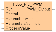


 F356_PID_PWM
PID processing with optional PWM output
PID processing is performed to keep the process value PV as close as possible to the set point value SP. In contrast to F355_PID_DUT, this instruction enables a PWM output (on-off output). Auto-tuning is also available to automatically calculate the PID control data Kp, Ti, and Td.

Input
Start condition
Control data
PID control parameters
Manipulated value MV, additional control mode area, auto-tuning related area and working area
When you execute the instruction for the first time, i.e. when the execution condition specified at Run turns to TRUE, the default values are written to the DUT members 1 to 9 of DUT .
Process value (-30000–30000)
Output
Pulse-width modulated output (optional, instead of manipulated value output)
Instead of using this F instruction, we recommend using the corresponding FP7 instruction: FP_PID
Abbreviations used when describing PID processing
Abbreviation |
What it stands for |
Also know as |
|---|---|---|
PV |
Process value | Actual value, measured value |
SP |
Set point value | Target value, set value |
MV |
Manipulated value | Output value, manipulated variable |
Ts |
Sampling time | Cycle time |
Ti |
Integral time | - |
Td |
Derivative time | - |
Kp |
Proportional gain | - |
AT |
Auto-tuning | - |
Before the second execution of FP_PID, you need to change the DUT members 1 to 9 of the DUT to the required values.
When the input at Run is executed, the data in the argument ParametersNonHold is initialized. If you want a value in the DUT to use non-default values, write the values into the DUT using a MOVE instruction, for example, which must be triggered continuously by a TRUE condition.
F356_PID_PWM must be executed once and only once per scan. Therefore, do not execute F356_PID_PWM in interrupt programs or loops.
Do not turn the execution condition to FALSE during PID processing. Otherwise, PID processing will be disabled.
If you do not want parallel PWM output cycles, e.g. to enable control of multiple objects, delay the start-up times accordingly, e.g. by employing a timer instruction.

The period (cycle) of the PWM output is the sampling time Ts (the frequency of the PWM output is 1/Ts) and the duty is the manipulated value MV in 0.01% units, e.g. MV = 10000 means a duty of 100%.
if any parameter of F356_Parameters_NonHold_DUT is out of range
if any parameter of F356_Parameters_NonHold_DUT is out of range
if the area specified with UpperLimit or LowerLimit is out of range
Control conditions: F356_Parameters_Hold_DUT
Set point value SP and the control parameters: F356_Parameters_Hold_DUT
Additional notes on auto-tuning:
The members AT_Progress in F356_Parameters_Hold_DUT and b1_AT_Complete in F356_Control_DUT are cleared at the rising edge of the auto-tuning signal.
When auto-tuning has completed successfully, the element b1_AT_Complete of F356_Control_DUT is set, and the auto-tuning done code is stored in the element AT_Progress of F356_Parameters_NonHold_DUT.
When auto-tuning is aborted, the parameters of Kp, Ti, and Td are not changed.
In the global variable list you define variables that can be accessed by all POUs in the project.


All input and output variables used for programming this function have been declared in the POU header. The same POU header is used for all programming languages.

_VAR
	VAR
		bStartAutoTuning: BOOL:=FALSE;
		bRunPidControl: BOOL:=FALSE;
		ControlData: F356_Control_DUT;
		ParametersHold: F356_Parameters_Hold_DUT;
		ParametersNonHold: F356_Parameters_NonHold_DUT;
	END_VAR

BODY
    WORKSPACE
        NETWORK_LIST_TYPE := NWTYPELD ;
        ACTIVE_NETWORK := 0 ;
    END_WORKSPACE
    NET_WORK
        NETWORK_TYPE := NWTYPELD ;
        NETWORK_LABEL :=  ;
        NETWORK_TITLE :=  ;
        NETWORK_HEIGHT := 5 ;
        NETWORK_BODY
B(B_CONTACT,,bStartAutoTuning,5,1,7,3,R);
B(B_COIL,,ControlData.b0_AT_Request,22,1,24,3,);
L(1,2,5,2);
L(7,2,22,2);
L(1,0,1,5);
        END_NETWORK_BODY
    END_NET_WORK
    NET_WORK
        NETWORK_TYPE := NWTYPELD ;
        NETWORK_LABEL :=  ;
        NETWORK_TITLE :=  ;
        NETWORK_HEIGHT := 7 ;
        NETWORK_BODY
B(B_F,F356_PID_PWM!,Instance,11,0,22,7,,?DRun?DControl?DParametersHold?DParametersNonHold?DProcessValue?APWM_Output);
B(B_VARIN,,ControlData,9,2,11,4,);
B(B_VARIN,,ParametersHold,9,3,11,5,);
B(B_VARIN,,ParametersNonHold,9,4,11,6,);
B(B_VARIN,,x_iTemperatureInput,9,5,11,7,);
B(B_VAROUT,,y_bPwmOutput,22,1,24,3,);
B(B_CONTACT,,bRunPidControl,4,1,6,3,);
L(1,2,4,2);
L(6,2,11,2);
L(1,0,1,7);
        END_NETWORK_BODY
    END_NET_WORK
END_BODY
(* Auto Tuning: *)
if DF(bStartAutoTuning) then
    ControlData.b0_AT_Request:=TRUE;
end_if;
y_bPwmOutput:=F356_PID_PWM(    Run := bRunPidControl,
        Control := ControlData,
        ParametersHold := ParametersHold,
        ParametersNonHold := ParametersNonHold,
        ProcessValue := x_iTemperatureInput);