


 F171_PulseOutput_Jog_Positioning
JOG operation and positioning
The specified number of pulses is output after the position control trigger input has turned to TRUE. A deceleration is performed before the target value is reached and pulse output stops.Pulses are output from the specified channel when the control flag for this channel is FALSE and the execution condition is TRUE.
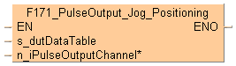
Input
Starting address of area containing the data table
F171_PulseOutput_Jog_Positioning_Type0_DUT or F171_PulseOutput_Jog_Positioning_Type1_DUTPulse output channel:0–3
Select one of two different operation modes:
Type 0: The speed can be changed within the range of the specified target speed.
Type 1: The target speed can be changed once when the position control trigger input turns to TRUE.
Pulse output characteristics

The pulse output frequency changes according to the specified acceleration time and the specified deceleration time.
The difference between target speed and initial speed determines the slope of the acceleration ramp.
The difference between target speed and final speed determines the slope of the deceleration ramp.
After the position control trigger input has turned to TRUE, pulse output continues, then decelerates and stops when the target value is reached.
Pulse output can be stopped by one of the following operations:
Turning the position control trigger to TRUE (pulse output continues until the target value has been reached and deceleration has completed): The position control trigger can be started by turning a position control trigger input to TRUE or by setting bit 6 of the data register storing the pulse output control code from FALSE to TRUE (e.g. MOVE(16#140, sys_wHscOrPulseControlCode);).
Requesting a decelerated stop: To perform a decelerated stop, set bit 5 of the data register storing the pulse output control code from FALSE to TRUE (e.g. MOVE(16#120, sys_wHscOrPulseControlCode);).When a decelerated stop is requested during acceleration, deceleration is performed with the same slope as deceleration from the target speed.
Executing an emergency stop: To perform an emergency stop, set bit 3 of the data register storing the pulse output control code from FALSE to TRUE (e.g. MOVE(16#108, sys_wHscOrPulseControlCode);).
When stopping, disable all pulse output functions for the channel used in the program.
Use the following predefined DUT: F171_PulseOutput_Jog_Positioning_Type0_DUT
The following parameters can be specified in the DUT:
Control code
Initial and final speed
Target speed
Acceleration time
Deceleration time
Target value
The target speed can be changed during pulse output.Changing the target speed during pulse output
Without changing the target speed: |
With changing the target speed: |
|
 |
Initial and final speed
Target speed
Target value
Acceleration time
Deceleration time
Execution condition
Position control trigger input
Pulse output control flag
To change the speed, keep the execution condition TRUE.
If the target speed is set to a value larger than 50kHz, it will be corrected to 50kHz.
If the elapsed value crosses over the acceleration forbidden area starting position (e.g. sys_diPulseChannel0AccelerationForbiddenAreaStartingPosition) during acceleration, acceleration cannot be performed.
The deceleration speed cannot be lower than the corrected final speed.
Changing the target speed is not possible if the instruction is executed in an interrupt program.
Use the following predefined DUT: F171_PulseOutput_Jog_Positioning_Type1_DUT
The following parameters can be specified in the DUT:
Control code
Initial and final speed
Target speed1
Acceleration time
Target speed2
Change time
Deceleration time
Target value
Target speed 1< target speed 2: |
Target speed 1> target speed 2: |
 |
 |
Initial and final speed
Target speed
Target speed
Target value
Acceleration time
Change time
Deceleration time
Execution condition
Position control trigger input
After the position control trigger input has turned to TRUE, the pulse output frequency will change using the change time to accelerate or decelerate to target speed 2. Further target speed changes are not possible. The position control trigger input will be disregarded if it is turned on during acceleration.
As soon as you begin editing a program online (i.e., in RUN mode) using this instruction, pulse output will stop.
If both the main program and the interrupt program contain code for the same channel, make sure both are not executed simultaneously.
When a pulse output instruction is executed and pulses are being output, the pulse output control flag (e.g. sys_bIsPulseChannel0Active) of the corresponding channel is TRUE. No other pulse output instruction can be executed as long as this flag is TRUE.
Set the position control trigger input (X0, X1, X2, X3) in system register 402.
For the position control trigger input, only the rising edge (TRUE) is detected.
The instruction cannot be started when a decelerated stop has been requested.
To restart after stopping the operation, turn the execution condition to FALSE and then to TRUE again.
We strongly recommend that you incorporate a forced stop option in your positioning program.
The status of the high-speed counter control flag or pulse output control flag may change while a scan is being carried out. For example, if the number of received bytes is read more than once different statuses may exist within one scan.

All input and output variables used for programming this function have been declared in the POU header. The same POU header is used for all programming languages.
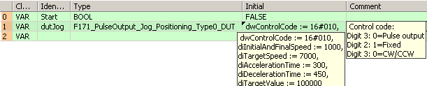
	VAR
		Start: BOOL:=FALSE;
		dutJog: F171_PulseOutput_Jog_Positioning_Type0_DUT:=dwControlCode := 16#010,
diInitialAndFinalSpeed := 1000,
diTargetSpeed := 7000,
diAccelerationTime := 300,
diDecelerationTime := 450,
diTargetValue := 10000;
			(*Digit3: 0=Pulse output
Digit2: 1=Fixed
Digit0: 0=CW/CCW2*)
		diInitialAndFinalSpeed: DINT:=1000;
		@'': @'';
	END_VAR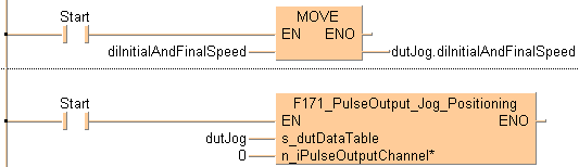
BODY
    WORKSPACE
        NETWORK_LIST_TYPE := NWTYPELD ;
        ACTIVE_NETWORK := 0 ;
    END_WORKSPACE
    NET_WORK
        NETWORK_TYPE := NWTYPELD ;
        NETWORK_LABEL :=  ;
        NETWORK_TITLE :=  ;
        NETWORK_HEIGHT := 5 ;
        NETWORK_BODY
B(B_F,E_MOVE!,Instance,13,0,19,4,,?DEN?D?AENO?C);
B(B_VARIN,,diInitialAndFinalSpeed,11,2,13,4,);
B(B_VAROUT,,dutJog.diInitialAndFinalSpeed,19,2,21,4,);
B(B_CONTACT,,Start,6,1,8,3,);
L(1,2,6,2);
L(8,2,13,2);
L(1,0,1,5);
        END_NETWORK_BODY
    END_NET_WORK
    NET_WORK
        NETWORK_TYPE := NWTYPELD ;
        NETWORK_LABEL :=  ;
        NETWORK_TITLE :=  ;
        NETWORK_HEIGHT := 5 ;
        NETWORK_BODY
B(B_F,F171_PulseOutput_Jog_Positioning!,Instance,8,0,24,5,,?DEN?Ds_dutDataTable?Hn_iPulseOutputChannel?AENO);
B(B_VARIN,,dutJog,6,2,8,4,);
B(B_VARIN,,0,6,3,8,5,);
B(B_CONTACT,,Start,2,1,4,3,);
L(1,2,2,2);
L(4,2,8,2);
L(1,0,1,5);
        END_NETWORK_BODY
    END_NET_WORK
END_BODYIF (Start) then
dutJog.diInitialAndFinalSpeed:=diInitialAndFinalSpeed;
END_IF;
IF (Start) then
F171_PulseOutput_Jog_Positioning(s_dutDataTable := dutJog, 0);
END_IF;